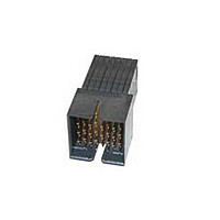
1934357-1 TE Connectivity, 1934357-1 Datasheet - Page 5

1934357-1
Manufacturer Part Number
1934357-1
Description
RA HEADER 3 PAIR / 10 COLUMN
Manufacturer
TE Connectivity
Datasheet
1.1934219-1.pdf
(8 pages)
Specifications of 1934357-1
Connector Type
Header
Pcb Mounting Orientation
Right Angle
Pcb Mount Retention
With
Termination Method To Pc Board
Through Hole - Press Fit
Pcb Mount Alignment
Without
Sealed
No
Ul File Number
E28476
Stackable
No
Module Type
Center
Data Rate (gb/s)
10.000
Differential Impedance (?)
100
Contact - Rated Current (a)
0.5
Hot Pluggable
No
Operating Voltage Reference
AC
Operating Voltage (vac)
250
Tail Length (mm [in])
2.2 [0.087]
Header Type
Partially Shrouded
Number Of Positions
90
Number Of Signal Positions
60
Number Of Rows
9
Number Of Columns
10
Pcb Mount Retention Type
Compliant Posts
Centerline (mm [in])
1.91 [0.075]
Row-to-row Spacing (mm [in])
1.40 [0.055]
Mating Retention
Without
Contact Type
Pin
Contact Design
Rectangular Post
Contact Base Material
Phosphor Bronze
Contact Plating, Mating Area, Material
Gold
Contact Plating, Mating Area, Thickness (µm [?in])
0.76 [29.92]
Tail Plating Material
Matte Tin
Tail Plating, Thickness (µm [?in])
0.5 [20]
Connector Style
Plug
End Wall Location
Open
Housing Color
Black
Mating Alignment
With
Mating Alignment Type
Guide Slot
Housing Material
Liquid Crystal Polymer (LCP)
Ul Flammability Rating
UL 94V-0
Number Of Pairs Per Connector
30
Pairs Per Column
3
Differential Signaling
With
Rohs/elv Compliance
RoHS compliant, ELV compliant
Lead Free Solder Processes
Not relevant for lead free process
Rohs/elv Compliance History
Always was RoHS compliant
Agency/standard
UL
Ul Rating
Recognized
Ul Voltage Rating (vac)
250
Operating Temperature (°c [°f])
-65 – +90 [-85 – +194]
Board-to-board Configuration
Co-Planar
Pcb Thickness, Recommended (mm [in])
1.57 [0.062]
Contact Transmits (typical Application)
Signal (Data)
Packaging Method
Tube
3.6.
.
Rev B
Product Qualification and Requalification Test Sequence
NOTE
Initial examination of product
Low level contact resistance
Low level compliant pin resistance
Insulation resistance
Withstanding voltage
Temperature rise vs current
Vibration
Mechanical shock
Durability
Mating force
Unmating force
Compliant pin insertion force
Compliant pin retention force
Minute disturbance
Thermal shock
Humidity-temperature cycling
Temperature life
Mixed flowing gas (mated)
Mixed flowing gas (unmated)
Dust contamination
Final examination of product
Test or Examination
(a)
(b)
(c)
(d)
(e)
See paragraph 4.1.A.
Numbers indicate sequence in which tests are performed.
Perform 10 durability cycles prior to initial measurement.
Perform 100 durability cycles before, and 100 durability cycles after mixed flowing gas
testing.
Exposure interval of 5 days.
3,6,8,10,12 3,5,7,9,11
2,14
4,13
11
15
1
1
9
5
7
Figure 2
2,12
2a
10
13
1
4
8
6
Test Sequence (b)
Test Group (a)
2b
1
6
7
2
4
5
3
8
4(c),6 2,4,6,8,10,12,14,16
3,7
3
1
2
8
5
9
3(d),15(d)
9(e),11(e)
5(e),7(e)
13
17
4
1
5
1
2
3
108-2303
5 of 8


