PAXLR000 Red Lion Controls, PAXLR000 Datasheet - Page 4
PAXLR000
Manufacturer Part Number
PAXLR000
Description
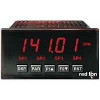
METER RATE INDICATION 6-DIGIT
Manufacturer
Red Lion Controls
Series
PAX®LITEr
Type
Rate Indicatorr
Specifications of PAXLR000
Count Rate
25kHz
Number Of Digits/alpha
6
Input Type
Logic, Transistor
Voltage - Supply
10 V ~ 16 VDC,115 VAC, 230 VAC
Display Type
LED
No. Of Digits / Alpha
6
Signal Input Type
Pulse
Character Size
0.56"
Ip/nema Rating
IP65 / NEMA 4X
Panel Cutout Height
1.77"
Display Font Color
Red
Panel Cutout Width
3.62"
Accuracy
±0.01% %
Connection Type
Cage-Clamp
Cut Out, Panel
3.62×1.77 "
Digit Height
0.56
Dimensions
4.2"L×3.8"W×1.95"H
Display Digit Height
0.56 "
Function
Rate Indicator
Number Of Digits
6
Primary Type
Electronic
Range, Measurement
0.01 Hz to 25 kHz
Termination
Terminal Block
Voltage, Supply
115/230 VAC
Counter Supply Voltage
115/230VAC/10-16VDC
Rohs Compliant
Yes
Lead Free Status / RoHS Status
Lead free / RoHS Compliant
Lead Free Status / RoHS Status
Lead free / RoHS Compliant, Lead free / RoHS Compliant
Other names
RLC103


applying power. To access the power switch, remove the meter base from the
case by firmly squeezing and pulling back on the side rear finger tabs. This
should lower the latch below the case slot (which is located just in front of the
finger tabs). It is recommended to release the latch on one side, then start the
other side latch.
Power Selection Switch
Set-Up DIP Switches
and is fully accessible when the unit is in the case.
It is used for the selection of the input parameters
and program disable.
SWITCH 1
SWITCH 2
WIRING OVERVIEW
back of the meter. All conductors should conform to the meter’s voltage and
current ratings. All cabling should conform to appropriate standards of good
installation, local codes and regulations. It is recommended that the power
supplied to the meter (DC or AC) be protected by a fuse or circuit breaker.
meter case against those shown in wiring drawings for proper wire position. Strip
the wire, leaving approximately 0.3" (7.5 mm) bare lead exposed (stranded wires
should be tinned with solder.) Insert the lead under the correct screw-clamp
terminal and tighten until the wire is secure. (Pull wire to verify tightness.)
EMC INSTALLATION GUIDELINES
Magnetic Interference (EMI), proper installation and wiring methods must be
followed to ensure compatibility in each application. The type of the electrical
noise, source or coupling method into the meter may be different for various
installations. The meter becomes more immune to EMI with fewer I/O
connections. Cable length, routing, and shield termination are very important
and can mean the difference between a successful or troublesome installation.
Listed below are some EMC guidelines for successful installation in an
industrial environment.
1. The meter should be mounted in a metal enclosure, which is properly
2. Use shielded (screened) cables for all Signal and Control inputs. The shield
2.0 S
3.0 W
The meter has switches that must be checked and/or changed prior to
A DIP switch is located at the rear of the meter,
SNK.: Adds internal 7.8 KΩ pull-up resistor to + 12 VDC, I
SRC.: Adds internal 3.9 KΩ pull-down resistor, 8 mA max. @ 30 VDC max.
Electrical connections are made via screw-clamp terminals located on the
When wiring the meter, compare the numbers embossed on the back of the
Although this meter is designed with a high degree of immunity to Electro-
connected to protective earth.
(screen) pigtail connection should be made as short as possible. The
connection point for the shield depends somewhat upon the application.
Listed below are the recommended methods of connecting the shield, in order
of their effectiveness.
a. Connect the shield only at the panel where the unit is mounted to earth
b. Connect the shield to earth ground at both ends of the cable, usually when
ground (protective earth).
the noise source frequency is above 1 MHz.
proper voltage before powering-up the meter. The meter is shipped
from the factory in the 230 VAC position.
Caution: Insure the AC power selection switch is set for the
ETTING THE
IRING THE
M
S
ON
1
WITCHES
Factory Setting
2
MAX
ETER
3
= 1.9 mA.
4
5
6
4
SWITCH 3
SWITCH 4
SWITCH 5
SWITCH 6
3. Never run Signal or Control cables in the same conduit or raceway with AC
4. Signal or Control cables within an enclosure should be routed as far as possible
5. In extremely high EMI environments, the use of external EMI suppression
6. Long cable runs are more susceptible to EMI pickup than short cable runs.
7. Switching of inductive loads produces high EMI. Use of snubbers across
HI Frequency: Removes damping capacitor and allows max. frequency.
LO Frequency: Limits input frequency to 50 Hz and input pulse widths
LOGIC: Input trigger levels V
MAG: 200 mV peak input (must have SRC on).
Enable Programming: Enables programming through the front panel buttons.
Disables Programming: Disables the front panel buttons from any
Not Active for the Rate Meter
c. Connect the shield to common of the meter and leave the other end of the
power lines, conductors feeding motors, solenoids, SCR controls, and
heaters, etc. The cables should be ran in metal conduit that is properly
grounded. This is especially useful in applications where cable runs are long
and portable two-way radios are used in close proximity or if the installation
is near a commercial radio transmitter.
from contactors, control relays, transformers, and other noisy components.
devices, such as ferrite suppression cores, is effective. Install them on Signal
and Control cables as close to the unit as possible. Loop the cable through the
core several times or use multiple cores on each cable for additional protection.
Install line filters on the power input cable to the unit to suppress power line
interference. Install them near the power entry point of the enclosure. The
following EMI suppression devices (or equivalent) are recommended:
Therefore, keep cable runs as short as possible.
inductive loads suppresses EMI.
to 10 msec.
programming changes.
shield unconnected and insulated from earth ground.
Ferrite Suppression Cores for signal and control cables:
Line Filters for input power cables:
Note: Reference manufacturer’s instructions when installing a line filter.
Snubber: RLC# SNUB0000.
Fair-Rite # 0443167251 (RLC# FCOR0000)
TDK # ZCAT3035-1330A
Steward # 28B2029-0A0
Schaffner # FN610-1/07 (RLC# LFIL0000)
Schaffner # FN670-1.8/07
Corcom # 1 VR3
SELECTION
POWER
SWITCH
REAR TERMINALS
230
115
FRONT DISPLAY
IL
= 1.5 V max.; V
INPUT SET-UP
DIP SWITCHES
IH
= 3.75 V max.