SCUBT-200/A Red Lion Controls, SCUBT-200/A Datasheet - Page 2
SCUBT-200/A
Manufacturer Part Number
SCUBT-200/A
Description
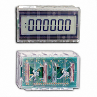
TIME/COUNTER 5 1/2 DIGIT
Manufacturer
Red Lion Controls
Series
SUB-CUBr
Datasheet
1.SCUBT-200A.pdf
(4 pages)
Specifications of SCUBT-200/A
Count Rate
500kHz
Number Of Digits/alpha
5
Input Type
Voltage
Voltage - Supply
2.5 V ~ 5.5 V
Display Type
LCD Non-Backlit
Lead Free Status / RoHS Status
Lead free / RoHS Compliant
Output Type
-
Other names
RLC07
SCUBT
SCUBT-200
SCUBT
SCUBT-200


DEVICE CONNECTIONS
SIG - CMOS input with series 4.7 K resistor.
C0-C3 - CMOS latched inputs. These inputs select the mode of operation of
WINK - CMOS output. Connect this output to either DP1 or DP2 input to
DP1 - LCD input. Connect this input to the WINK output to enable the first
DP2 - LCD input. Connect this input to the WINK output to enable the
BP - CMOS output. Connect this output to either DP1 or DP2 to disable a
V
V
* All unused inputs must be tied to V
CAUTION
handling to the same degree required by standard CMOS integrated circuits.
Units should be stored in the conductive packaging used to ship the devices.
Containers should be opened and units handled only on a conductive table
top by personnel wearing wrist-strap grounding equipment. These devices
have the same protection circuits as standard CMOS devices to prevent
damage to inputs due to nominal over-voltage.
DD
SS
Timer Modes - SUB-CUB-T accumulates time when SIG is at V
Counter Modes - SUB-CUB-T increments a count on the rising edge of
the SUB-CUB-T. Refer to “MODE SELECTION”.
enable a decimal point.
position decimal point. Connect to BP to disable this decimal point.
second position decimal point. Connect to BP to disable this decimal
point.
decimal point.
This device contains CMOS circuitry which requires special anti-static
- Common for D.C. Supply and Inputs.
- 2.5 to 5.5 VDC supply.
SUB-CUB-T stops timing when SIG is at V
the SIG input.
ELECTRICAL CHARACTERISTICS V
* An internal 4.7 K series resistor will protect the SIG input from input voltages up to 9.7 V AC or DC (w/V
** Inputs C0-C3 are latched internally and will draw little or no current after switching. During switching, a 90 µA peak
SYMBOL
T
FHS
TRS
V
ICO
FLS
At higher input voltages, an external resistor should be used to limit the input current to less than 1 mA.
current may be drawn for up to 10 nS.
I
V
V
I
ACC
DD
SS
DD
IH
IL
SS
Count Speed w/o Debounce
or V
Count Speed w/Debounce
*
Control Input Current
Signal Input Current
Input High Voltage
Reset Pulse Width
Input Low Voltage
DD
Timer Accuracy
Supply Voltage
Supply Current
, whichever is appropriate.
PARAMETER
SS
.
MIN.
100
DD
2.5
3.5
DD
= 5 V ±10% UNLESS OTHERWISE SPECIFIED
,
2
TYP.
500
1.0
30
5
MAXIMUM RATINGS (VOLTAGE REF. TO V
RATING
DC Supply Voltage
Input Voltage, All Inputs except SIG
Input Voltage, SIG Input only
Operating Temperature*
Storage Temperature
* Extended high and low temperature ranges available, consult factory.
MAX.
15.0
0.05
5.5
9.7
1.5
3.0
90
40
10
UNIT
KHz
µA
µA
µA
Hz
µS
%
V
V
V
BLOCK DIAGRAM
*
TEST CONDITION
Signal @ V
** C0-C3 @ V
Modes 4, 6, 8, & 10.
Modes 5, 7, 9, & 11.
All time ranges.
SYMBOL
T
V
V
DD
T
V
STG
DD
IS
A
I
or V
DD
DD
or V
SS
-0.3 to (V
= 5.0).
SS
-35 to +85
-35 to +85
VALUE
6.0
9.7
SS
DD
)
+0.3)
VAC or DC
UNIT
o
o
V
V
C
C