SCUBT-200/A Red Lion Controls, SCUBT-200/A Datasheet - Page 3
SCUBT-200/A
Manufacturer Part Number
SCUBT-200/A
Description
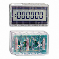
TIME/COUNTER 5 1/2 DIGIT
Manufacturer
Red Lion Controls
Series
SUB-CUBr
Datasheet
1.SCUBT-200A.pdf
(4 pages)
Specifications of SCUBT-200/A
Count Rate
500kHz
Number Of Digits/alpha
5
Input Type
Voltage
Voltage - Supply
2.5 V ~ 5.5 V
Display Type
LCD Non-Backlit
Lead Free Status / RoHS Status
Lead free / RoHS Compliant
Output Type
-
Other names
RLC07
SCUBT
SCUBT-200
SCUBT
SCUBT-200


MODE SELECTION
or in one of eight counting modes. Mode selection is accomplished by
connecting the four CONTROL inputs (C0, C1, C2, & C3) to the appropriate
voltage level (Where 0 = V
TIMER OPERATION
(See Mode Selection Chart). When operated as a timer, the SUB-CUB-T
display will show “00000” when initially reset. The SUB-CUB-T will start to
accumulate time at the selected time interval when the SIG input is connected
to V
time that SIG is held high. When the LCD display reaches 99999, the display
will increment to 100000. A maximum display of 199999 can be displayed. On
the next time interval, the display will wrap around to 00000.
COUNTER OPERATION
modes; four modes with debounce and four modes without debounce (See
Mode Selection Chart). When operated as a counter, the SUB-CUB-T will reset
to 00000 and will increment on the rising edge of the SIG input. A maximum
of 199999 counts can be displayed before the SUB-CUB-T wraps around to
00000.
TYPICAL APPLICATION
which is capable of measuring and recording both partical counts and sample
time. The partical counts should be measured in units of 1,000. The counter
should be able to accept a signal rate of up to 1,000 counts per second. An
elapsed time indicator measuring time in 1/100 of hours is needed to report the
length of sampling time. A RUN switch should enable both the counter and
the timer. A common RESET switch should clear both units. Both devices
must be able to operate from a 4.5 VDC battery pack and must consume a
minimum of power to prolong battery life.
COUNTER should be operated in the “÷1000 Count w/o Debounce” mode
(Mode 11). The 0 to 4.5 VDC output pulse of the Partical Sensor can be
* The reset mode (Mode 15) can be used to reset the Timer/Counter to 0.
The SUB-CUB-T can be programmed to operate in one of four timing modes
The SUB-CUB-T can be programmed to operate in one of four time intervals
The SUB-CUB-T can be programmed to operate in one of eight count
MODE
DD
An equipment builder has been contracted to supply a hand-held device
The SUB-CUB-T can be used to satisfy both requirements.
10
11
12
13
14
15
The SUB-CUB-T should NOT be left in this mode for longer than a few
seconds; otherwise damage to the LCD may result.
0
1
2
3
4
5
6
7
8
9
. The COLON LCD segments will flash at a 1 Hz rate for the period of
C3
0
0
0
0
0
0
0
0
1
1
1
1
1
1
1
1
C2
0
0
0
0
1
1
1
1
0
0
0
0
1
1
1
1
SS
, and 1 = V
C1
0
0
1
1
0
0
1
1
0
0
1
1
0
0
1
1
PORTABLE PARTICAL COUNTER WITH ELAPSED TIME INDICATOR
C0
0
1
0
1
0
1
0
1
0
1
0
1
0
1
0
1
DD
). Refer to the chart below.
MODE DESRIPTION
Hours Timer
0.1 Hours Timer
0.01 Hours Timer
0.1 Minutes Timer
X1 Counter w/Debounce
X1 Counter w/o Debounce
÷10 Counter w/Debounce
÷10 Counter w/o Debounce
÷100 Counter w/Debounce
÷100 Counter w/o Debounce
÷1000 Counter w/Debounce
÷1000 Counter w/o Debounce
Factory Test Modes
Reset Mode *
The
3
connected directly to the counter input. Both DP1 and DP2 are connected to
the BP output to disable the decimal points. The TIMER should be operated
in the “0.01 Hours” mode (Mode 2). The SIG input is enabled when the RUN
switch is closed. The 100 K pull-down resistor will disable the SIG input
when the RUN switch is opened. The value of this resistor is kept high to
reduce power consumption. DP2 is enabled by connecting it to the WINK
output. DP1 is disabled by connecting it to the BP output.
COUNTER and the TIMER are cleared by pressing the RESET button. This
will place the SUB-CUB-T’s in the RESET mode (Mode 15). When the
RESET switch is opened, both units will return to their normal modes of
operation.
DECIMAL POINT SELECTION
position or the second position, as well as no decimal point. If selected, the
decimal point will flash at a 1 Hz rate (along with the LCD COLON) in all timer
modes while the SIG input is activated. When the SIG input is de-activated, the
selected decimal point will remain “ON”. Use the following table to determine
the proper connections for the desired decimal point position.
TYPICAL APPLICATION
AC MOTOR RUN TIME
a motor for service purposes. The timer must be capable of operating
directly from the power line and must be able to record time in 1/10 hour
increments.
T can accept either an AC or DC signal input, no blocking diodes are
required. To protect the SIG input from damage due to overvoltage, R1 is
used to limit the input current to less than 1 mA.
The SUB-CUB-T is capable of displaying a decimal point in either the first
An equipment manufacturer is interested in knowing the total run time of
The SUB-CUB-T can be used in this application. Since the SUB-CUB-
DISPLAY
0000.0
000.00
00000
CONNECT TO WINK
CONNECT TO BP
CONNECT TO BP
DP2
CONNECT TO WINK
CONNECT TO BP
CONNECT TO BP
DP1
Both the