MC100LVEP111FAG ON Semiconductor, MC100LVEP111FAG Datasheet - Page 10
MC100LVEP111FAG
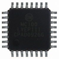
Manufacturer Part Number
MC100LVEP111FAG
Description
IC CLOCK DRIVER DIFF 1:10 32LQFP
Manufacturer
ON Semiconductor
Series
100LVEPr
Type
Fanout Buffer (Distribution), Multiplexerr
Datasheet
1.MC100LVEP111FARG.pdf
(13 pages)
Specifications of MC100LVEP111FAG
Number Of Circuits
1
Ratio - Input:output
2:10
Differential - Input:output
Yes/Yes
Input
ECL, HSTL, LVDS, PECL
Output
ECL, PECL
Frequency - Max
3GHz
Voltage - Supply
2.375 V ~ 3.8 V
Operating Temperature
-40°C ~ 85°C
Mounting Type
Surface Mount
Package / Case
32-LQFP
Frequency-max
3GHz
Output Logic Level
ECL, PECL
Supply Voltage (max)
+/- 3.8 V
Supply Voltage (min)
+/- 2.375 V
Maximum Operating Temperature
+ 85 C
Minimum Operating Temperature
- 40 C
Mounting Style
SMD/SMT
Multiply / Divide Factor
2:1
Number Of Clock Inputs
2
Mode Of Operation
Differential
Output Frequency
3000MHz
Operating Supply Voltage (min)
-2.375/2.375V
Operating Supply Voltage (typ)
-2.5/-3.3/2.5/3.3V
Operating Supply Voltage (max)
-3.8/3.8V
Package Type
LQFP
Operating Temp Range
-40C to 85C
Operating Temperature Classification
Industrial
Signal Type
ECL/HSTL/PECL
Mounting
Surface Mount
Pin Count
32
Lead Free Status / RoHS Status
Lead free / RoHS Compliant
Other names
MC100LVEP111FAGOS
Available stocks
Company
Part Number
Manufacturer
Quantity
Price
Company:

Part Number:
MC100LVEP111FAG
Manufacturer:
ON
Quantity:
3
Company:
Part Number:
MC100LVEP111FAG
Manufacturer:
ON Semiconductor
Quantity:
10 000


†For information on tape and reel specifications, including part orientation and tape sizes, please refer to our Tape and Reel Packaging
ORDERING INFORMATION
Specifications Brochure, BRD8011/D.
MC100LVEP111FA
MC100LVEP111FAG
MC100LVEP111FAR2
MC100LVEP111FARG
M100LVEP111FATW
M100LVEP111FATWG
MC100LVEP111MNG
MC100LVEP111MNRG
Quadrant B = Upper Right
Quadrant D = Lower Right
Quadrant C = Lower Left
Quadrant A = Upper Left
Device
Designations
(See Application Note AND8020/D − Termination of ECL Logic Devices.)
Figure 11. Typical Termination for Output Driver and Device Evaluation
Driver
Device
Figure 12. Tape and Reel Pin 1 Quadrant Orientation
Q
Q
(Pb−Free)
(Pb−Free)
(Pb−Free)
(Pb−Free)
(Pb−Free)
LQFP−32
LQFP−32
LQFP−32
LQFP−32
LQFP−32
LQFP−32
Package
QFN−32
QFN−32
Quadrant
Quadrant
Z
Z
http://onsemi.com
A
C
o
o
= 50 W
= 50 W
10
50 W
V
Quadrant
Quadrant
TT
= V
D
B
V
CC
TT
− 2.0 V
(Pin 1 Orientation in Quadrant B, Figure 12)
(Pin 1 Orientation in Quadrant B, Figure 12)
(Pin 1 Orientation in Quadrant A, Figure 12)
(Pin 1 Orientation in Quadrant A, Figure 12)
50 W
User Direction
of Unreeling
2000 / Tape & Reel
2000 / Tape & Reel
2000 / Tape & Reel
2000 / Tape & Reel
1000 / Tape & Reel
250 Units / Tray
250 Units / Tray
D
D
74 Units / Rail
Shipping
Receiver
Device
Round Sprocket Holes
†
Related parts for MC100LVEP111FAG
Image
Part Number
Description
Manufacturer
Datasheet
Request
R

Part Number:
Description:
ON Semiconductor [VOLTAGE REGULATOR]
Manufacturer:
ON Semiconductor
Datasheet:
Part Number:
Description:
357-036-542-201 CARDEDGE 36POS DL .156 BLK LOPRO
Manufacturer:
ON Semiconductor
Datasheet:
Part Number:
Description:
357-036-542-201 CARDEDGE 36POS DL .156 BLK LOPRO
Manufacturer:
ON Semiconductor
Datasheet:
Part Number:
Description:
357-036-542-201 CARDEDGE 36POS DL .156 BLK LOPRO
Manufacturer:
ON Semiconductor
Datasheet:
Part Number:
Description:
357-036-542-201 CARDEDGE 36POS DL .156 BLK LOPRO
Manufacturer:
ON Semiconductor
Datasheet:
Part Number:
Description:
357-036-542-201 CARDEDGE 36POS DL .156 BLK LOPRO
Manufacturer:
ON Semiconductor
Datasheet:
Part Number:
Description:
357-036-542-201 CARDEDGE 36POS DL .156 BLK LOPRO
Manufacturer:
ON Semiconductor
Datasheet:
Part Number:
Description:
357-036-542-201 CARDEDGE 36POS DL .156 BLK LOPRO
Manufacturer:
ON Semiconductor
Datasheet:
Part Number:
Description:
357-036-542-201 CARDEDGE 36POS DL .156 BLK LOPRO
Manufacturer:
ON Semiconductor
Datasheet:
Part Number:
Description:
357-036-542-201 CARDEDGE 36POS DL .156 BLK LOPRO
Manufacturer:
ON Semiconductor
Datasheet:
Part Number:
Description:
357-036-542-201 CARDEDGE 36POS DL .156 BLK LOPRO
Manufacturer:
ON Semiconductor
Datasheet:
Part Number:
Description:
Manufacturer:
ON Semiconductor
Datasheet:
Part Number:
Description:
Manufacturer:
ON Semiconductor
Datasheet:
Part Number:
Description:
Manufacturer:
ON Semiconductor
Datasheet: