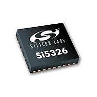
SI5326A-C-GM Silicon Laboratories Inc, SI5326A-C-GM Datasheet - Page 70

SI5326A-C-GM
Manufacturer Part Number
SI5326A-C-GM
Description
IC ANY-RATE MULTI/ATTEN 36-QFN
Manufacturer
Silicon Laboratories Inc
Type
Clock Multiplierr
Datasheet
1.SI5326B-C-GM.pdf
(72 pages)
Specifications of SI5326A-C-GM
Package / Case
36-QFN
Pll
Yes
Input
Clock
Output
CML, CMOS, LVDS, LVPECL
Number Of Circuits
1
Ratio - Input:output
2:2
Differential - Input:output
Yes/Yes
Frequency - Max
1.4GHz
Divider/multiplier
Yes/Yes
Voltage - Supply
1.71 V ~ 3.63 V
Operating Temperature
-40°C ~ 85°C
Mounting Type
Surface Mount
Frequency-max
1.4GHz
Max Input Freq
710 MHz
Max Output Freq
945 MHz
Maximum Operating Temperature
+ 85 C
Minimum Operating Temperature
- 40 C
Mounting Style
SMD/SMT
Number Of Outputs
2
Supply Current
251 mA
Supply Voltage (max)
3.3 V
Supply Voltage (min)
1.8 V
Lead Free Status / RoHS Status
Lead free / RoHS Compliant
Lead Free Status / RoHS Status
Lead free / RoHS Compliant, Lead free / RoHS Compliant
Available stocks
Company
Part Number
Manufacturer
Quantity
Price
Part Number:
SI5326A-C-GMR
Manufacturer:
SILICON LABS/芯科
Quantity:
20 000
Si5326
D
Revision 0.1 to Revision 0.2
Revision 0.2 to Revision 0.3
Revision 0.3 to Revision 0.4
Revision 0.4 to Revision 0.41
70
OCUMENT
Updated LVTTL to LVCMOS is Table 2, “Absolute
Maximum Ratings,” on page 6.
Added Figure 3, “Typical Phase Noise Plot,” on page
16.
Updated Figure 4, “Si5326 Typical Application
Circuit (I
Typical Application Circuit (SPI Control Mode),” on
page 17 to show preferred external reference
interface.
Updated “5.Register Map”.
Updated "8. Ordering Guide" on page 65.
Added "9. Package Outline: 36-Pin QFN" on page
66.
Added “10.Recommended PCB Layout”.
Changed 1.8 V operating range to ±5%.
Updated Table 1 on page 4.
Updated Table 2 on page 6.
Updated Table 11 on page 66.
Added table under Figure 3 on page 16.
Updated "4. Functional Description" on page 18.
Clarified "5. Register Map" on page 20 including pull-
up/pull-down.
Updated Table 1 on page 4.
Added "11. Si5326 Device Top Mark" on page 69.
Changed “latency” to “skew” throughout.
Updated Table 1 on page 4.
Updated Figure 4 on page 17.
Updated Figure 5, “Si5326 Typical Application
Circuit (SPI Control Mode),” on page 17.
Updated "5. Register Map" on page 20.
Updated "9. Package Outline: 36-Pin QFN" on page
66.
Added Figure 9, “Ground Pad Recommended
Layout,” on page 67
Added Register Map
Added RATE0 and changed RATE to RATE1 and
expanded RATE[1:0] description.
Changed font of register names to underlined italics.
Updated Thermal Resistance Junction to Ambient
typical specification.
2
C Control Mode),” and Figure 5, “Si5326
C
HANGE
L
IST
Rev. 1.0
Revision 0.41 to Revision 0.42
Revision 0.42 to Revision 0.43
Revision 0.43 to Revision 0.44
Revision 0.44 to Revision 1.0
Text added to section "5. Register Map" on page 20.
Replaced Figure 9.
Updated Rise/Fall time values.
Changed register address labels to decimal.
Updated first page format to add chip image and pin
out
Updated Functional Block Diagram
Updated Section “1.Electrical Specifications” to
include ac/dc specifications from the Si53xx Family
Reference Manual (FRM)
Updated typical phase noise performance in Section
“2.Typical Phase Noise Performance”
Added INC/DEC pins to Figure 4 and Figure 5
Clarified the format for FLAT [14:0]
Added list of weak pull up/down resistors in Table 10,
“Si5326 Pull up/Pull down,” on page 64
Updated register maps 19, 20, 46, 47, 55, 142, 143,
185
Added note to typical application circuits in Section
“3.Typical Application Circuit”
Added evaluation board part number to “8.Ordering
Guide”
Updated Section “11.Si5326 Device Top Mark”
Updated Table 5, “Jitter Generation,” on page 14;
filled in all TBDs, and lowered typical RMS values


