1-1473005-4 TE Connectivity, 1-1473005-4 Datasheet - Page 2
1-1473005-4
Manufacturer Part Number
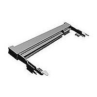
1-1473005-4
Description
SEMI-HARD TRAY DDR2 SODIMM SOCKET 200P 5
Manufacturer
TE Connectivity
Specifications of 1-1473005-4
Socket Style
SO DIMM
Dram Type
Double Data Rate (DDR)
Pcb Mount Style
Surface Mount
Module Orientation
Right Angle
Profile
Standard
Keying
Standard
Dram Voltage
1.8 V
Solder Tail Contact Plating
Gold Flash
Socket Type
Memory Card
Number Of Positions
200
Row-to-row Spacing (mm [in])
6.20 [0.244]
Centerline (mm [in])
0.60 [0.024]
Number Of Rows
Dual
Ejector Type
Locking
Ejector Location
Both Ends
Number Of Keys
1
Latch Material
Stainless Steel
Latch Plating
Tin
Boss
Without
Mount Type
Printed Circuit Board
Contact Plating, Mating Area, Material
Gold Flash
Contact Base Material
Copper Alloy
Housing Material
High Temperature Thermoplastic
Housing Color
Black
Ul Flammability Rating
UL 94V-0
Stack Height (mm [in])
5.20 [0.205]
Insertion Style
Cam-In
Center Key (mm [in])
None
Rohs/elv Compliance
RoHS compliant, ELV compliant
Lead Free Solder Processes
Reflow solder capable to 245°C
Rohs/elv Compliance History
Always was RoHS compliant
Application Type
DDR SDRAM
Packaging Method
Semi-Hard Tray Assembly
Packaging Quantity
20


3.4 Performance Requirements and Test Descriptions :
3.5 Test Requirements and Procedures Summary
3.5.1
3.5.2
3.5.3
3.5.4
Para.
3.5.5
Rev. F
3.3 Ratings :
C.
Para.
D. Floating Peg
The product shall be designed to meet the electrical, mechanical and environmental performance
requirements specified in Fig. 1. All tests shall be performed in the room temperature, unless otherwise
specified.
A. Voltage Rating :
B. Current Rating :
C. Temperature Rating :9 55 ° C to 85 ° C
Stainless Steal
Latch :
Copper Alloy, Tin Plated
Examination of Product
Termination Resistance
(Low Level)
Dielectric withstanding
Voltage
Insulation Resistance
Test Items
Vibration
(Low Frequency)
Test Items
25 VAC
0.5 A
Meets requirements of product
drawing
30 m Æ Max. (Initial)
∆R=20 m Æ Max. (Final)
No creeping discharge nor
flashover shall occur.
Current leakage : 0.5 mA Max.
250M Æ Min.(Initial)
50M Æ Min.(Final)
Requirements
No electrical discontinuity
greater than 0.1 sec. shall
occur.
∆R=20 m Æ Max. (Final)
Product Specification
Mechanical Requirements
Electrical Requirements
Requirements
Visual inspection
No physical damage
Subject mated contacts assembled in
housing to closed circuit current of 10 mA
Max. at open circuit voltage of 20mV Max.
obtain resistance value by dividing the
measured reading into two.
Fig. 3-1,3-2.
AMP Spec. 109-5311-1
0.25 kVAC for 1 minute.
Test between adjacent circuits of unmated
connectors.
AMP Spec. 109-5301
Impressed voltage 500 V DC.
Test between adjacent circuits of unmated
connectors.
AMP Spec. 109-5302
Procedures
Subject mated connectors to 10-55-10 Hz
traversed in 1 minute at 1.52 mm
amplitude
2 hours each of 3 mutually perpendicular
planes.
100 mA applied.
AMP Spec. 109-5201
Procedures
108-5701
2 of 5
Related parts for 1-1473005-4
Image
Part Number
Description
Manufacturer
Datasheet
Request
R

Part Number:
Description:
Conn Wire to Board HDR 14 POS 2.54mm Solder ST Thru-Hole
Manufacturer:
TE Connectivity
Datasheet:

Part Number:
Description:
Conn Shrouded Header HDR 14 POS 2mm Solder ST Thru-Hole
Manufacturer:
TE Connectivity
Datasheet:

Part Number:
Description:
Pluggable Terminal Blocks 10P STR GRN 30-14
Manufacturer:
TE Connectivity
Datasheet:

Part Number:
Description:
DYNAMIC D-3 REC CONT 3L 16-14
Manufacturer:
TE Connectivity
Datasheet:
Part Number:
Description:
DYNAMIC D-3 REC CONT. 2L 16-14
Manufacturer:
TE Connectivity
Datasheet:

Part Number:
Description:
Manufacturer:
TE Connectivity
Datasheet:

Part Number:
Description:
Manufacturer:
TE Connectivity
Datasheet:

Part Number:
Description:
Manufacturer:
TE Connectivity
Datasheet:

Part Number:
Description:
Manufacturer:
TE Connectivity
Datasheet:

Part Number:
Description:
Manufacturer:
TE Connectivity
Datasheet:

Part Number:
Description:
Manufacturer:
TE Connectivity
Datasheet:

Part Number:
Description:
Manufacturer:
TE Connectivity
Datasheet:

Part Number:
Description:
Manufacturer:
TE Connectivity
Datasheet:

Part Number:
Description:
Manufacturer:
TE Connectivity
Datasheet:

Part Number:
Description:
Manufacturer:
TE Connectivity
Datasheet: