1-1473005-4 TE Connectivity, 1-1473005-4 Datasheet - Page 3
1-1473005-4
Manufacturer Part Number
1-1473005-4
Description
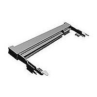
SEMI-HARD TRAY DDR2 SODIMM SOCKET 200P 5
Manufacturer
TE Connectivity
Specifications of 1-1473005-4
Socket Style
SO DIMM
Dram Type
Double Data Rate (DDR)
Pcb Mount Style
Surface Mount
Module Orientation
Right Angle
Profile
Standard
Keying
Standard
Dram Voltage
1.8 V
Solder Tail Contact Plating
Gold Flash
Socket Type
Memory Card
Number Of Positions
200
Row-to-row Spacing (mm [in])
6.20 [0.244]
Centerline (mm [in])
0.60 [0.024]
Number Of Rows
Dual
Ejector Type
Locking
Ejector Location
Both Ends
Number Of Keys
1
Latch Material
Stainless Steel
Latch Plating
Tin
Boss
Without
Mount Type
Printed Circuit Board
Contact Plating, Mating Area, Material
Gold Flash
Contact Base Material
Copper Alloy
Housing Material
High Temperature Thermoplastic
Housing Color
Black
Ul Flammability Rating
UL 94V-0
Stack Height (mm [in])
5.20 [0.205]
Insertion Style
Cam-In
Center Key (mm [in])
None
Rohs/elv Compliance
RoHS compliant, ELV compliant
Lead Free Solder Processes
Reflow solder capable to 245°C
Rohs/elv Compliance History
Always was RoHS compliant
Application Type
DDR SDRAM
Packaging Method
Semi-Hard Tray Assembly
Packaging Quantity
20


3.5.6
3.5.7
Para.
3.5.8
3.5.9
3.5.10
3.5.11
Para.
3.5.12
3.5.13
3.5.14
Rev. F
Physical Shock
P.C.Board Mating Force
Test Items
Durability
(Repeated
Mate/Unmating)
Solder ability
Resistance to Reflow
Soldering Heat
Thermal Shock
Test Items
Humidity-Temperature
Cycling
Salt Spray
Industrial Gas (SO2)
No electrical discontinuity
greater than 0.1 sec. shall
occur.
∆R=20 m Æ Max. (Final)
200 Pos. : 59.8N (6.1 kgf) Max.
Requirements
∆R=20 m Æ Max. (Final)
Wet Solder Coverage :
95 % Min.
No physical damage shall
occur
∆R=20 m Æ Max. (Final)
∆ 4
∆ 4
∆ 4
4 G S W K T G O G P V U
+ P U W N C V K Q P T G U K U V C P E G
Environmental Requirements
Product Specification
O Æ / C Z
O Æ / C Z
O Æ / C Z
/ Æ / K P H K P C N
( K P C N
( K P C N
( K P C N
Accelerated Velocity : 490 m/s
Waveform
Duration : 11 m sec.
Number of Drops: 3 drops each to normal
and reversed directions of X, Y and Z
axes, totally 18 drops.
AMP Spec. 109-5208
Condition A
Operation Speed : 100 mm/min.
Measure the force required to mate
connectors.(In this test, the force required
to turn PCB before it engages on lacking,
is excluded.)
AMP Spec. 109-5206
Procedures
Repeated insertion and extraction of P.C.B
to and from the connector with the turns to
lock it and then unlock it for 25 cycles.
Solder Temperature : 245 r 5 ° C
Immersion Duration : 5 r 0.5 seconds
Flux : Alpha 100
AMP Spec. 109-5203
Test connector on P.C.Board
Mated connector
9 55°C / 30 min.,
85° C / 30 min.
Making this a cycle, repeat 5 cycles.
AMP Spec. 109-5103 Condition A
Procedures
Mated connector, 25:* 65°C,
90:* 95 % R. H. 5 cycles
Cold shock 9 10° C performed
AMP Spec. 109-5106
Subject mated connectors to 5 % salt
concentration for 24 hours :
AMP Spec. 109-5101
Mated connector
SO2 Gas : 10 ppm, 95 % R. H.
25° C, 24 hours
AMP Spec. 109-5107
Pre-Heat150:* 180 ‘ :90 r 30sec.
Heat 230 ‘ Min.
Heat Peak260 ‘ Max. See Fig.4-2
OR
Apply to JEDEC standard
(J-STD-020C)
: Half sine
Condition B
:30 r 10sec.
Condition A
Condition A
2
108-5701
(50 G)
3 of 5
Related parts for 1-1473005-4
Image
Part Number
Description
Manufacturer
Datasheet
Request
R

Part Number:
Description:
Conn Wire to Board HDR 14 POS 2.54mm Solder ST Thru-Hole
Manufacturer:
TE Connectivity
Datasheet:

Part Number:
Description:
Conn Shrouded Header HDR 14 POS 2mm Solder ST Thru-Hole
Manufacturer:
TE Connectivity
Datasheet:

Part Number:
Description:
Pluggable Terminal Blocks 10P STR GRN 30-14
Manufacturer:
TE Connectivity
Datasheet:

Part Number:
Description:
DYNAMIC D-3 REC CONT 3L 16-14
Manufacturer:
TE Connectivity
Datasheet:
Part Number:
Description:
DYNAMIC D-3 REC CONT. 2L 16-14
Manufacturer:
TE Connectivity
Datasheet:

Part Number:
Description:
Manufacturer:
TE Connectivity
Datasheet:

Part Number:
Description:
Manufacturer:
TE Connectivity
Datasheet:

Part Number:
Description:
Manufacturer:
TE Connectivity
Datasheet:

Part Number:
Description:
Manufacturer:
TE Connectivity
Datasheet:

Part Number:
Description:
Manufacturer:
TE Connectivity
Datasheet:

Part Number:
Description:
Manufacturer:
TE Connectivity
Datasheet:

Part Number:
Description:
Manufacturer:
TE Connectivity
Datasheet:

Part Number:
Description:
Manufacturer:
TE Connectivity
Datasheet:

Part Number:
Description:
Manufacturer:
TE Connectivity
Datasheet:

Part Number:
Description:
Manufacturer:
TE Connectivity
Datasheet: