1-968855-1 TE Connectivity, 1-968855-1 Datasheet
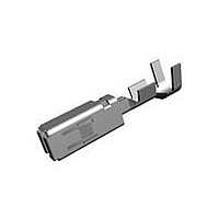
MCP2,8 SOCKET CONT SWS

1-968855-1

Manufacturer Part Number
1-968855-1
Description
MCP2,8 SOCKET CONT SWS
Manufacturer
TE Connectivity
Series
HDSCS, J2557 Connector System, Multiple Contact Point (MCP), Standard Timerr
Datasheets

Specifications of 1-968855-1

Rohs Compliant
YES
Product Type
Contact
Mating Area Interface Dimensions (mm [in])
2.79 x 0.81 [.110 x .032]
Wire/cable Type
Regular Wire
Insulation Support
With
Wire Range (mm [awg])
0.50-1.00² [20-17]
Single Wire Sealing System
Yes
Single Seal Part No.
828904-1
Contact Type
Socket
Contact Base Material
CuNiSi
Contact Plating, Mating Area, Material
Pre-Tin
Rohs/elv Compliance
RoHS compliant, ELV compliant
Lead Free Solder Processes
Not relevant for lead free process
Rohs/elv Compliance History
Always was RoHS compliant
Applies To
Wire/Cable
Cavity Plug Part No.
828922
Packaging Method
Strip

Available stocks

Company
Part Number
Manufacturer
Quantity
Price
Part Number:
1-968855-1
Manufacturer:
TE
Quantity:
108 000
Part Number:
1-968855-1
Manufacturer:
SMD
Quantity:
35 000
1.
1.1.
1.2.
2.
2.1.
2.2.
3.
3.1.
©2011 Tyco Electronics Corporation,
a TE Connectivity Ltd. Company
All Rights Reserved
TE logo is a trademark.
SCOPE
Content
This specification covers perform ance, tests and quality requirem ents for the TE Connectrivity (TE)
Power Distribution Module Assem bly (PDM), produced for use in Arctic Cat Off Road vehicles. The
PDM consists of a 4X10 contact pattern base, part num ber 109853-1, and cover with seal, part num ber
109854-1. The PDM contact pattern, 8.13 m m contact spacing, is that of Tyco Electronics VJ28-95F24
relay, and autom otive MINI fuse system , intended for use in this application. The purpose of this
docum ent is to determ ine the capability of Tyco supplied com ponents.
Qualification
W hen tests are perform ed on the subject product line, procedures specified in Figure 1 shall be used.
All inspections shall be perform ed using the applicable inspection plan and product drawing.
APPLICABLE DOCUM ENTS
The following docum ents form a part of this specification to the extent specified herein. Unless
otherwise specified, the latest edition of the docum ent applies. In the event of conflict between the
requirem ents of this specification and the product drawing, the product drawing shall take precedence.
In the event of conflict between the requirem ents of this specification and the referenced docum ents,
this specification shall take precedence.
TE Docum ents
!
!
!
Industry Standards
!
!
!
!
REQUIREM ENTS
Design and Construction
Product shall be of the design, construction and physical dim ensions specified on the applicable product
drawing.
108-18513: Product Specification
109-197: TE Test Specifications vs EIA and IEC Test Methods
501-543: Qualification Test Report
EIA-364: Electrical Connector/Socket Test Procedures Including Environm ental Classifications
IEC 60512: Electrom echanical Com ponents For Electronic Equipm ent; Basic Testing Procedures
and Measuring Methods Part 1: General
IEC 60529: Degrees of Protection Provided by Enclosures (IP Code)
SAE J1455: Joint SAE/TMC Recom m ended Environm ental Practices for Electronic Equipm ent
Design (Heavy-duty Trucks)
| Indicates change
*Trademark
Product
Specification
Power Distribution Module Assembly
For latest revision, visit our website at www.te.com/documents.
For Regional Customer Service, visit our website at www.te.com
Other products, logos, and company names might be trademarks of their respective owners.
108-47001
11Mar11 Rev A
1 of 8
LOC B

Related parts for 1-968855-1

1-968855-1 Summary of contents

Page 1

... Tyco supplied com ponents. 1.2. Qualification W hen tests are perform ed on the subject product line, procedures specified in Figure 1 shall be used. All inspections shall be perform ed using the applicable inspection plan and product drawing. 2. APPLICABLE DOCUM ENTS The following docum ents form a part of this specification to the extent specified herein ...

Page 2

... W ire seal: Silicone rubber 3.3. Ratings ! Current: Refer to TE MCP 2 term inal system , part num ber 1-968857-1 sealed term inal 14 part num ber 1-968855-1 sealed term inal for electrical rating and heat rise characteristics ! Tem perature: -40 to 65°C !. Seal: Dust proof, SAEJ1455, 4.7.3, splash proof ...

Page 3

... See Note. Figure 1 (continued) 108-47001 Procedure Drop from a height [3.28 ft] onto a concrete floor on 3 corners and flat on latches. Two corners at bottom of cover (closed corners), 1 corner at seal area. Affixed to 750 m m [29.53 in] cable length, 40 wires m axim um , routed sym m etrically, dropped 8 tim es from 750 m m [29 ...

Page 4

... NOTE tests as specified in the Product Qualification and Requalification Test Sequence shown in Figure 2. Rev A Requirem ent Inserted contact m ust withstand a m inim um force [17.98 lbf] before disengagem ent from cavity, when pulled by the wire. All contact cavities to be tested. ENVIRONMENTAL See Note. ...

Page 5

... Resistance to vibrations Mechanical shock Durability Housing locking m echanism strength Contact retention strength Tem perature life Resistance to therm al shocks. Hum idity Dust bom bardm ent W ater tightness (a) See paragraph 4.1.A. NOTE (b) Numbers indicate sequence in which tests are performed. Rev A Test Group ( Test Sequence (b) ...

Page 6

... Acceptance Acceptance is based on verification that the product m eets the requirem ents of Figure 1. Failures attributed to equipm ent, test setup or operator deficiencies shall not disqualify the product. If product failure occurs, corrective action shall be taken and specim ens resubm itted for qualification. Testing to confirm corrective action is required before resubm ittal ...

Page 7

... Fuse, 10A Hi-Beam : A9 and A10 Fuse, 10A Lo-Beam : A7 and A8 Diode, 1A Neutral: D1 and D2 Diode, 1A Reverse: A1 and A2 1.0 am pere All fuse and diodes 10 am peres and less - wire peres - wire peres - wire Decal picture provided for illustration only. Spare fuses are not to be used in testing and NOTE unused contact cavities to be plugged with TE plugs part number 828922-1. Data shows time the main fuse contact reaches 80° ...

Page 8

... Linear slopes on log-log plots only. RMS G Level - 3.2 G's. Maximum G level limited the RMS level. Tolerance: ± from 10 to 2000 Hz. Figure 5 Vibration Profile 108-47001 Slope Between Breakpoints 0.0 -5.42 0.0 -9.20 -20.02 -100.12 ...

Related keywords