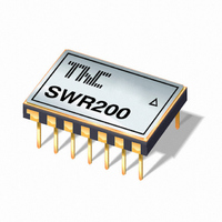
SWR200C Cirrus Logic Inc, SWR200C Datasheet - Page 4

SWR200C
Manufacturer Part Number
SWR200C
Description
IC SINE WAVE REF PREC 7V 14-DIP
Manufacturer
Cirrus Logic Inc
Type
Sine Wave Referencer
Datasheet
1.SWR200C.pdf
(5 pages)
Specifications of SWR200C
Frequency
10kHz
Voltage - Supply
±15 V
Current - Supply
10.5mA
Operating Temperature
-25°C ~ 85°C
Package / Case
14-DIP
Mounting Style
Through Hole
Lead Free Status / RoHS Status
Lead free / RoHS Compliant
Count
-
Lead Free Status / Rohs Status
Lead free / RoHS Compliant
SWR200
3. THEORY OF OPERATION
The following refers to the schematic in Figure 1. A1 and A2 are connected as a phase-shift oscillator circuit with
the frequency set by the external capacitors C1 and C2. Q4 is included in the feedback loop of A1 as a gain control
element.
The oscillator output is fed to the chopper amplifier which develops an absolute value representation of the oscillator
output. The chopper output is compared to a precision DC reference in integrator amplifier A3. This DC error signal
is used ot control the gain setting FET Q4.
As in all precision zener based DC references, the drift of the zener becomes nonlinear at temperature extremes.
The chopper amplifier drift characteristic is complementary to this nonlinearity and compensates for the reference
drift.
4. APPLICATION INFORMATION
Figure 1 shows the connections for the SWR200 including the two frequency setting capacitors. The frequency is:
The frequency stability is directly related to the stability of the capacitors, therefore stable capacitors like NPO
ceramic, polycarbonate or polypropylene film should be used. Specified device operation relies on the tight match-
ing of capacitors C1 and C2. The capacitor mismatch must not exceed 10% over the entire operating temperature
range. The recommended capacitor tolerance is 5% or less to ensure specified electrical performance.
Two separate ground pins are provided for accurate ground sensing. This minimizes errors due to drops in the
ground pin which can become a significant source of error in sockets.
The offset of the SWR200 is fully specified for initial offset and drift and is low enough that it can normally be ne-
glected. In applications which are especially sensitive to offset the output can be AC coupled. Proper capacitor siz-
ing and high impedance sensing will minimize errors due to capacitive coupling.
Figure 1. External Connections
5. EXTENDED FREQUENCY RANGE
The SWR200 with two external frequency setting capacitors is fully specified for operation from 400Hz to 10KHz. At
lower frequencies, the limitations occurs in the AGC circuit that provides the high amplitude stability of the SWR200.
There is also a slight increase in distortion from 1500Hz down to 400Hz, which continues as frequency
decreases.
Two external capacitors can increase the time constant of the AGC circuit allowing for use at lower frequencies. This
increase in time constant comes with the tradeoff of a longer settling time from power on.
4
f =
P r o d u c t T e c h n o l o g y F r o m
C
10
1
C
-5
Figure 2. Pin Configuration
2
GND
-PS
C1
NC
NC
C1
NC
TOP VIEW
SWR200
+PS
GND SENSE
C2
NC
NC
OUTPUT
C2
SWR200DS


