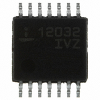
ISL12032IVZ-T Intersil, ISL12032IVZ-T Datasheet - Page 14

ISL12032IVZ-T
Manufacturer Part Number
ISL12032IVZ-T
Description
IC RTC LP BATT BACK SRAM 14TSSOP
Manufacturer
Intersil
Type
Clock/Calendar/NVSRAMr
Datasheet
1.ISL12032IVZ-T.pdf
(26 pages)
Specifications of ISL12032IVZ-T
Memory Size
1K (128 x 8)
Time Format
HH:MM:SS:hh (12/24 hr)
Date Format
YY-MM-DD-dd
Interface
I²C, 2-Wire Serial
Voltage - Supply
2.7 V ~ 5.5 V
Operating Temperature
-40°C ~ 85°C
Mounting Type
Surface Mount
Package / Case
14-TSSOP
Lead Free Status / RoHS Status
Lead free / RoHS Compliant
Other names
ISL12032IVZ-TTR
Available stocks
Company
Part Number
Manufacturer
Quantity
Price
Company:
Part Number:
ISL12032IVZ-T
Manufacturer:
Intersil
Quantity:
11 856
BATTERY ACTIVE MODE (BMODE)
BMODE Indicates that the device is operating from the VBAT
input. A “1” indicates Battery Mode and a “0” indicates power
from V
device must be in VBAT mode in order for a valid “1” read
from this bit.
DAYLIGHT SAVING TIME ADJUSTMENT BIT (DSTADJ)
DSTADJ is the Daylight Saving Time Adjustment Bit. It
indicates that daylight saving time adjustment has
happened. The bit will be set to “1” when the Forward DST
event has occurred. The bit will stay set until the Reverse
DST event has happened. The bit will also reset to “0” when
the DSTE bit is set to “0” (DST function disabled). The bit
can be forced to “1” with by writing “F0h” to the Status
Register. The default value for DSTADJ is “0”.
ALARM BITS (ALM0 AND ALM1)
These bits announce if an alarm matches the real time clock.
If there is a match, the respective bit is set to “1”. This bit can
be manually reset to “0” by the user or automatically reset by
enabling the auto-reset bit (see ARST bit). A write to this bit in
the SR can only set it to “0”, not “1”. An alarm bit that is set by
an alarm occurring during an SR read operation will remain
set after the read operation is complete.
LOW V
Indicates V
(Brownout Mode). The Trip points for Brownout levels are
selected by three bits VDDTrip2, VDDTrip1 and VDDTrip0 in
the PWRVDD registers.
LOW BATTERY INDICATOR 85% BIT (LBAT85)
Indicates battery level dropped below the pre-selected trip
level (85% of battery voltage). The trip point is set by three
bits: VB85Tp2, VB85Tp1 and VB85Tp0 in the PWRBAT
register.
LOW BATTERY INDICATOR 75% BIT (LBAT75)
Indicates battery level dropped below the pre-selected trip
level (75% of battery voltage). The trip point is set by three
bits: VB75Tp2, VB75Tp1 and VB75Tp0 in the PWRBAT
register.
REAL TIME CLOCK FAIL BIT (RTCF)
This bit is set to a “1” after a total power failure. This is a read
only bit that is set by hardware (internally) when the device
powers up after having lost all power (defined as V
and VBAT = 0V). The bit is set regardless of whether V
VBAT is applied first. The loss of only one of the supplies
does not set the RTCF bit to “1”. The first valid write to the
RTC section after a complete power failure resets the RTCF
bit to “0” (writing one byte is sufficient).
ADDR
08h
DD
DD
BMODE DSTADJ ALM1 ALM0 LVDD LBAT85 LBAT75 RTCF
mode. The I2CBAT bit must be set to “1” and the
7
TABLE 2. STATUS REGISTER DC (SRDC)
INDICATOR BIT (LVDD)
DD
dropped below the pre-selected trip level.
6
5
14
4
3
2
DD
1
= 0V
DD
0
or
ISL12032
Status Register (SRAC)
The Status Register AC is located in the memory map at
address 09h. This is a volatile register that provides status of
Crystal Failure (XOSCF), AC Failed (ACFAIL) and AC
Ready (ACRDY).
CRYSTAL OSCILLATOR FAIL BIT (XOSCF)
Indicates Crystal Oscillator has stopped if XOSCF = 1. When
the crystal oscillator has resumed operation, the XOSCF bit
is reset to “0”.
AC FAIL (ACFAIL)
This bit announces the status of the AC input. If ACFAIL = 1,
then the AC input frequency and amplitude qualification
check has failed. ACFAIL is reset to “0” when the AC input
meets the preset requirements (see “AC (AC Input)” on
page 8).
AC READY (ACRDY)
This bit announces the status of the AC input. If ACRDY = 1,
then the AC input has passed the qualification parameter
check (as set by ACFC and ACFP bits) for the time
prescribed by ACRP and is used for the RTC clock. When
ACRDY = 0 the AC input failed the qualification
requirements and the crystal oscillator clock is used for the
RTC clock (see “AC (AC Input)” on page 8).
When ACFAIL transitions from “1” to “0” (from failed to pass),
then the timer set by ACRP will determine the delay until
ACRDY transitions from “0” to “1”. ACRDY will be set to “0”
immediately after ACRDY is set to “0” (failed AC input),
indicating the crystal oscillator is the RTC clock.
Counter Registers
Addresses [0Ah to 0Bh]
These registers will count the number of times AC failure
occurs and the number of times an event occurs. These
registers are 8-bits each and will count up to 255.
AC COUNT (ACCNT)
The ACCNT register increments automatically each time the
AC input switches to the crystal backup. The register is set to
00h on initial power-up. The maximum count is 255, and will
stay at that value until set to zero via an I
ADDR
ADDR
0Ah
09h
AXC7
TABLE 4. AC COUNTER REGISTER (ACCNT)
TABLE 3. STATUS REGISTER AC (SRAC)
7
X
7
AXC6
6
X
6
5
X
AXC5
5
XOSCF
4
AXC4
4
3
X
AXC3
3
2
2
X
C write.
AXC2
2
ACFAIL
1
AXC1
April 16, 2009
1
ACRDY
FN6618.2
0
AXC0
0


