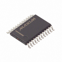
DS1318E+ Maxim Integrated Products, DS1318E+ Datasheet

DS1318E+
Specifications of DS1318E+
Related parts for DS1318E+
DS1318E+ Summary of contents
Page 1
... Register ♦ Square-Wave Output with 16 Selectable Frequencies from 32.768kHz to 0.5Hz ♦ +3.3V Operation ♦ Industrial Temperature Range: -40°C to +85°C ♦ Underwriters Laboratories (UL) Recognized PART DS1318E+ DS1318E+T&R + Denotes a lead(Pb)-free/RoHS-compliant package. T&R = Tape and reel. TOP VIEW X1 0.1μF X2 GND EXT ...
Page 2
Parallel-Interface Elapsed Time Counter ABSOLUTE MAXIMUM RATINGS Voltage Range on any Pin Relative to Ground ......-0.3V to +6.0V Operating Temperature Range ...........................-40°C to +85°C Storage Temperature Range .............................-55°C to +125°C PACKAGE THERMAL CHARACTERISTICS (Note 1) TSSOP (multilayer board) Junction-to-Ambient Thermal ...
Page 3
Parallel-Interface Elapsed Time Counter DC ELECTRICAL CHARACTERISTICS ( 3.7V -40°C to +85°C, unless otherwise noted.) (Note 2) CC BAT A PARAMETER SYMBOL Battery Input Current (ENOSC = 1) Battery Input Current I BATDR (ENOSC ...
Page 4
Parallel-Interface Elapsed Time Counter A0–A4 DQ0–DQ7 A0– DQ0–DQ7 A0– DQ0–DQ7 4 _____________________________________________________________________ CEA t CEL t OE OEA t OEL VALID Write Cycle Timing, Write-Enable Controlled t WC VALID t ...
Page 5
Parallel-Interface Elapsed Time Counter PF(MAX) V PF(MIN) t VCCF RECOGNIZED INPUTS VALID OUTPUTS POWER-UP/POWER-DOWN CHARACTERISTICS (T = -40°C to +85°C) (Note 2) A PARAMETER SYMBOL Recovery at Power-Up V Fall Time PF(MAX ...
Page 6
Parallel-Interface Elapsed Time Counter AC TEST CONDITIONS PARAMETER Input Pulse Levels Output Load Including Scope and Jig Input and Output Timing Measurement Reference Levels Input-Pulse Rise and Fall Times WARNING: Under no circumstances are negative undershoots, of any amplitude, allowed ...
Page 7
Parallel-Interface Elapsed Time Counter X1 32,768Hz CRYSTAL OSCILLATOR AND PRESCALER COUNTER X2 EXT LEVEL DETECT, CC POWER SWITCH, V AND WRITE PROTECT BAT BYTE-WIDE RAM INTERFACE A3–A0 DQ7–DQ0 _____________________________________________________________________ 32,768Hz 4,096Hz CLOCK CONTROL CIRCUITRY ...
Page 8
Parallel-Interface Elapsed Time Counter PIN NAME Connections for Standard 32.768kHz Quartz Crystal. The internal oscillator circuitry is designed for 1 X1 operation with a crystal having a 12.5pF specified load capacitance (C oscillator and can optionally be connected to an ...
Page 9
Parallel-Interface Elapsed Time Counter Table 2. Crystal Specifications* PARAMETER Nominal Frequency Series Resistance Load Capacitance * The crystal, traces, and crystal input pins should be isolated from RF generating signals. Refer to Application Note 58: Crystal Considerations for Dallas Real-Time ...
Page 10
Parallel-Interface Elapsed Time Counter Table 3. Address Map ADDRESS BIT 7 BIT 6 BIT 5 00h SS3 SS2 01h SS11 SS10 02h S7 S6 03h S15 S14 04h S23 S22 05h S31 S30 06h ALM7 ALM6 ALM5 07h ALM15 ALM14 ...
Page 11
Parallel-Interface Elapsed Time Counter BIT 7 BIT 6 BIT 5 TE ENOSC CCFG1 Special-Purpose Registers The DS1318 has three additional registers (control A, control B, and status) that control the clock, alarms, square wave, and interrupt output. The subseconds0 register ...
Page 12
Parallel-Interface Elapsed Time Counter BIT 7 BIT 6 BIT 5 PRS3 PRS2 PRS1 Bits Periodic Rate Select (PRS3–PRS0). When the oscillator is enabled (ENOSC = 1) the PF flag is set at the rates determined by the ...
Page 13
Parallel-Interface Elapsed Time Counter BIT 7 BIT 6 BIT 5 OSF UIP Bit 7: Oscillator Stop Flag (OSF). A logic 1 in this bit indicates that the oscillator either is or was stopped for some period of time and may ...
Page 14
Parallel-Interface Elapsed Time Counter Chip Information PROCESS: CMOS SUBSTRATE CONNECTED TO GROUND 14 ____________________________________________________________________ Package Information For the latest package outline information and land patterns www.maxim-ic.com/packages. Note that a “+”, “#”, or “-” in the package code indicates ...
Page 15
... Maxim cannot assume responsibility for use of any circuitry other than circuitry entirely embodied in a Maxim product. No circuit patent licenses are implied. Maxim reserves the right to change the circuitry and specifications without notice at any time. Maxim Integrated Products, 120 San Gabriel Drive, Sunnyvale, CA 94086 408-737-7600 ____________________ 15 © 2010 Maxim Integrated Products DESCRIPTION in the Recommended DC Operating Conditions table ...


