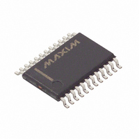
DS1318E+ Maxim Integrated Products, DS1318E+ Datasheet - Page 13

DS1318E+
Manufacturer Part Number
DS1318E+
Description
IC COUNTER ELAPSED TIME 24-TSSOP
Manufacturer
Maxim Integrated Products
Type
Elapsed Time Counterr
Datasheet
1.DS1318E.pdf
(15 pages)
Specifications of DS1318E+
Time Format
Binary
Date Format
Binary
Interface
Parallel
Voltage - Supply
3 V ~ 3.6 V
Operating Temperature
-40°C ~ 85°C
Mounting Type
Surface Mount
Package / Case
24-TSSOP
Lead Free Status / RoHS Status
Lead free / RoHS Compliant
Memory Size
-
Bit 7: Oscillator Stop Flag (OSF). A logic 1 in this bit
indicates that the oscillator either is or was stopped for
some period of time and may be used to judge the
validity of the timekeeping data. This bit is set to logic 1
any time the oscillator stops. The following are exam-
ples of conditions that can cause the OSF bit to be set:
1)
2)
3)
4)
Any write to the status register while this flag is active
clears the bit to 0.
Bit 6: Update-In-Progress Flag (UIP). A logic 1 in the
update-in-progress bit indicates that the internal clock
registers may be in the process of updating the user
registers. Writing to any seconds or subseconds regis-
ters when this bit is logic 1 may cause a collision with
the internal update and corrupt one or more of the user
registers until the next update occurs. If the UIP bit is
read and is logic 0, the user has at least 60µs to write
to the device without the possibility of causing a colli-
sion with the internal update. The internal timekeeping
update is gated by the falling edge of UIP.
Reading the subseconds and or seconds registers
while UIP is logic 1 may result in reading inconstant val-
ues. If the UIP bit is read and is logic 0, the user has at
least 60µs to read from the device without the possibili-
ty of getting inconstant values.
BIT 7
The first time power is applied.
The voltage present on both V
insufficient to support oscillation.
The ENOSC bit is turned off in battery-backed
mode.
External influences on the crystal (i.e., noise, leak-
age, etc.)
OSF
8kHz
4kHz
UIP
60μs
Parallel-Interface Elapsed Time Counter
BIT 6
UIP
BIT 5
0
____________________________________________________________________
CC
and V
BIT 4
BAT
0
is
Bit 1: Periodic Flag (PF). The periodic flag bit is set to
1 at the rate determined by the PRS bits in register 0Bh.
If the PF bit is already 1 when the selected frequency
attempts to set it to 1 again, no change occurs. The
user must clear the PIF flag faster than the part
attempts to set it to see the desired PF rate. If the PIE
bit in register 0Ah is also set to logic 1, the IRQ pin is
driven low in response to PF transitioning to 1. Any
write to the status register while this flag is active clears
the bit to 0.
Bit 0: Alarm Flag (ALMF). A logic 1 in the alarm flag
bit indicates that the contents of the seconds registers
matched the contents of the alarm registers. If the AIE
bit in register 0Ah is also set to logic 1, the IRQ pin is
driven low in response to ALMF transitioning to 1. Any
write to the status register while this flag is active clears
the bit to 0.
BIT 3
0
BIT 2
0
UIP vs. Update Timing
Status Register (0Ch)
BIT 1
PF
ALMF
BIT 0
13


