DS1743WP-120+ Maxim Integrated Products, DS1743WP-120+ Datasheet
DS1743WP-120+
Specifications of DS1743WP-120+


Related parts for DS1743WP-120+


DS1743WP-120+ Summary of contents
Page 1
FEATURES Integrated NV SRAM, Real-Time Clock, Crystal, Power-Fail Control Circuit, and Lithium Energy Source Clock Registers are Accessed Identically to the Static RAM. These Registers Reside in the Eight Top RAM Locations. Century Byte Register ...
Page 2
PIN DESCRIPTION PIN NAME PDIP PowerCap N.C. 31– A12 ...
Page 3
... DS1743W-120+ 0°C to +70°C DS1743W-120 IND+ -40°C to +85°C DS1743W-150+ 0°C to +70°C DS1743W-150 IND+ -40°C to +85°C DS1743WP-120+ 0°C to +70°C DS1743WP-120 IND+ -40°C to +85°C DS9034PCX 0°C to +70°C DS9034I-PCX -40°C to +85°C DS9034PCX+ 0°C to +70°C DS9034I-PCX+ -40° ...
Page 4
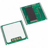
PACKAGES The DS1743 is available in two packages: the 28-pin DIP and the 34-pin PowerCap module. The 28-pin DIP-style module integrates the crystal, lithium energy source, and silicon all in one package. The 34-pin PowerCap Module Board is designed with ...
Page 5
Figure 1. Block Diagram Table 1. Truth Table CE V CE2 > < V < ...
Page 6
CLOCK ACCURACY (DIP MODULE) The DS1743 is guaranteed to keep time accuracy to within 1 minute per month at +25C. The RTC is calibrated at the factory by Dallas Semiconductor using nonvolatile tuning elements, and does not require additional calibration. ...
Page 7
WRITING DATA TO RAM OR CLOCK The DS1743 is in the write mode whenever WE, and CE are in their active state. The start of a write is referenced to the latter occurring transition of WE, on CE. The addresses ...
Page 8
ABSOLUTE MAXIMUM RATINGS Voltage Range on Any Pin Relative to Ground……………………………………………………-0.3V to +6.0V Operating Temperature Range…………………………………………………………………….-40°C to +85°C Storage Temperature Range……………………………………………………………………….-40°C to +85°C Soldering Temperature (EDIP) (leads, 10 seconds)…………………….……………………………..…+260°C Soldering Temperature…………………………………………..….See J-STD-020 Specification (See Note 8) This is a stress ...
Page 9
DC ELECTRICAL CHARACTERISTICS (3.3V) = 3.3V 10 Over the Operating Range PARAMETER Active Supply Current TTL Standby Current ( CMOS Standby Current (CE V - 0.2V; CC CE2 = GND + 0.2V) ...
Page 10
AC CHARACTERISTICS—READ CYCLE (3.3V) = 3.3V 10 Over the Operating Range PARAMETER Read Cycle Time Address Access Time CE and CE2 Low to DQ Low-Z CE and CE2 Access Time CE and CE2 Data-Off time ...
Page 11
AC CHARACTERISTICS—WRITE CYCLE (5V) = 5.0V 10 Over the Operating Range PARAMETER SYMBOL Write Cycle Time Address Setup Time WE Pulse Width CE Pulse Width CE2 Pulse Width Data Setup Time Data Hold Time CE ...
Page 12
WRITE CYCLE TIMING—WRITE-ENABLE CONTROLLED (See Note 5) WRITE CYCLE TIMING— CE /CE2-CONTROLLED (See Note 5) DS1743/DS1743P Y2K-Compliant, Nonvolatile Timekeeping RAMs ...
Page 13
POWER-UP/DOWN CHARACTERISTICS—5V = 5.0V 10 Over the Operating Range PARAMETER CE2 Before IH IL Power-Down V Fall Time PF(MAX) PF(MIN) V Fall ...
Page 14
POWER-UP/DOWN CHARACTERISTICS—3.3V = 3.3V 10 Over the Operating Range PARAMETER Before IH Power-Down V Fall Time PF(MAX) PF(MIN) V Rise Time ...
Page 15
AC TEST CONDITIONS Output Load 1TTL Gate Input Pulse Levels 3.0V Timing Measurement Reference Levels: Input: 1.5V Output: 1.5V Input Pulse Rise and Fall Times: 5ns NOTES: 1) Voltages are referenced to ground. 2) Typical ...
Page 16
... No circuit patent licenses are implied. Maxim/Dallas Semiconductor reserves the right to change the circuitry and specifications without notice at any time The Maxim logo is a registered trademark of Maxim Integrated Products, Inc. The Dallas logo is a registered trademark of Dallas Semiconductor. DS1743/DS1743P Y2K-Compliant, Nonvolatile Timekeeping RAMs DOCUMENT NO ...