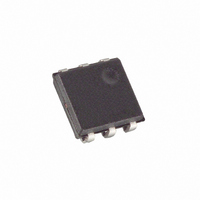
DS2417P+T&R Maxim Integrated Products, DS2417P+T&R Datasheet - Page 8

DS2417P+T&R
Manufacturer Part Number
DS2417P+T&R
Description
IC TIMECHIP W/INTRPT 1WIRE 6TSOC
Manufacturer
Maxim Integrated Products
Type
Time Chipr
Datasheet
1.DS2417P.pdf
(15 pages)
Specifications of DS2417P+T&R
Time Format
Binary
Date Format
Binary
Interface
1-Wire Serial
Voltage - Supply
2.5 V ~ 5.5 V
Operating Temperature
-40°C ~ 85°C
Mounting Type
Surface Mount
Package / Case
6-TSOC
Lead Free Status / RoHS Status
Lead free / RoHS Compliant
Memory Size
-
DS2417
INITIALIZATION
All transactions on the 1-Wire bus begin with an initialization sequence. The initialization sequence con-
sists of a reset pulse transmitted by the bus master followed by presence pulse(s) transmitted by the
slave(s). The presence pulse lets the bus master know that the DS2417 is on the bus and is ready to
operate. For more details, see the “1-Wire Signaling” section.
ROM FUNCTION COMMANDS
Once the bus master has detected a presence, it can issue one of the four ROM function commands that
the DS2417 supports. All ROM function commands are eight bits long. A list of these commands
follows (refer to flowchart in Figure 7):
Read ROM [33h]
This command allows the bus master to read the DS2417’s 8-bit family code, unique 48-bit serial num-
ber, and 8-bit CRC. This command should only be used if there is a single slave on the bus. If more than
one slave is present on the bus, a data collision will occur when all slaves try to transmit at the same time
(open drain will produce a wired-AND result). The resultant family code and 48-bit serial number read
by the master will be invalid.
Match ROM [55h]
The match ROM command, followed by a 64-bit ROM sequence, allows the bus master to address a spe-
cific DS2417 on a multidrop bus. Only the DS2417 that exactly matches the 64-bit ROM sequence will
respond to the following clock function command. All slaves that do not match the 64-bit ROM
sequence will wait for a reset pulse. This command can be used with a single or multiple devices on the
bus.
SEARCH ROM [F0h]
When a system is initially brought up, the bus master might not know the number of devices on the 1-
Wire bus or their 64-bit ROM codes. The search ROM command allows the bus master to use a process
of elimination to identify the 64-bit ROM codes of all slave devices on the bus. The search ROM process
is the repetition of a simple 3-step routine: read a bit, read the complement of the bit, then write the de-
sired value of that bit. The bus master performs this three-step routine on each bit of the ROM. After one
complete pass, the bus master knows the 64-bit ROM code of one device. Additional passes will identify
the ROM codes of the remaining devices. See Application Note 187 for a comprehensive discussion of a
search ROM, including an actual example.
Skip ROM [CCh]
This command can save time in a single drop bus system by allowing the bus master to access the clock
functions without providing the 64-bit ROM code. If more than one slave is present on the bus and, for
example, a read command is issued following the Skip ROM command, data collision will occur on the
bus as multiple slaves transmit simultaneously (open-drain pulldowns will produce a wired-AND result).
8 of 15


