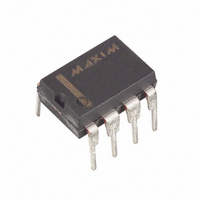
DS1678+ Maxim Integrated Products, DS1678+ Datasheet - Page 19

DS1678+
Manufacturer Part Number
DS1678+
Description
IC REAL TIME EVENT REC 8-DIP
Manufacturer
Maxim Integrated Products
Type
Time Event Recorderr
Datasheet
1.DS1678STR.pdf
(25 pages)
Specifications of DS1678+
Memory Size
32B
Time Format
HH:MM:SS (12/24 hr)
Date Format
YY-MM-DD-dd
Interface
I²C, 2-Wire Serial
Voltage - Supply
4.5 V ~ 5.5 V
Operating Temperature
-40°C ~ 85°C
Mounting Type
Through Hole
Package / Case
8-DIP (0.300", 7.62mm)
Lead Free Status / RoHS Status
Lead free / RoHS Compliant
Bit 3: Rollover (RO). This bit determines whether the data log function of the DS1678 rolls over or stops
writing data to the event-log memory if the event-log memory is completely filled. If RO is set to one, the
event-log memory rolls over after all 2048 bytes in the event-log memory have been used. After the
1024th event recorded in the event-log memory, the following sample has the full time/date stamp
information written to the Start Time Stamp register and the contents of the ETC written to the two bytes
following the start time stamp (Event 0 Rollover Stamp). The next sample has the duration of time from
the new start time stamp value written to event-log memory address locations 0000h and 0001h,
overwriting the original data. Likewise, subsequent samples increment through the event-log registers,
overwriting their data.
The Event 0 Rollover Stamp has the elapsed time since the last event in the event-log memory. This is to
allow the user to recover the information prior to the rollover. At the start of a mission, the value in these
two bytes is zero since there was no previous event from which to have an elapsed time.
If RO is set to zero, no further event logs are written to the event-log memory after all event-log memory
registers have been filled. However, events continue to be recognized, and the Event Counter Register is
incremented for each event.
Bits 2 and 1: Trigger Sel ect 0 and 1 (TR1 and TR0). These bits select the edge(s) that activate INT to
cause an event to be logged. An event can be triggered one of three ways, depending on the settings of the
TRx bits in the Control Register. With TR0 set to one and TR1 set to zero, INT is activated on the falling
edge of the input signal. With TR0 set to zero and TR1 set to one, the INT is activated on the rising edge
of the input signal.
With TR0 and TR1 set to zero, INT is activated by the rising and falling edges to allow for the
measurement and duration of on/off type events. If TR0 and TR1 are set to zero, nothing happens when
INT is toggled, and a mission does not start. This is an illegal state, and the mission does not start without
a valid value in the TRx bits prior to attempting to start the mission.
Table 6. Trigger Select Bits
Bit 0: Enable Oscillator (EOSC). This bit allows the clock oscillator to shut off to save power. The RTC
no longer keeps time when the oscillator is shut off, but the information stored in the device memory is
maintained. An event-log mission cannot start with EOSC set to zero, and the RTC must be reset to the
correct value after the oscillator is restarted and prior to starting a mission to obtain good data. A clear
memory also cannot be executed without the oscillator running. When V
automatically starts, no matter what the value in the EOSC bit, to allow proper communications.
Disabling the oscillator with EOSC can be used to extend the battery life whenever time and date
operation on battery backup is not required.
TR1 TR0
0
0
1
1
0
1
0
1
Nothing, Illegal State
Falling Edge
Rising Edge
Both Rising and Falling Edges
TRIGGER AN EVENT
EDGE(S) USED TO
19 of 25
CC
> V
BAT
, the oscillator


