DS1603+ Maxim Integrated Products, DS1603+ Datasheet - Page 3
DS1603+
Manufacturer Part Number
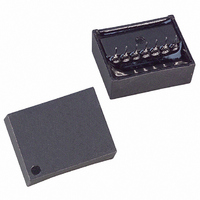
DS1603+
Description
IC COUNTER ELAPSED TIME 5V 7-SIP
Manufacturer
Maxim Integrated Products
Type
Elapsed Time Counterr
Datasheet
1.DS1603.pdf
(9 pages)
Specifications of DS1603+
Time Format
Binary
Date Format
Binary
Interface
3-Wire Serial
Voltage - Supply
4.5 V ~ 5.5 V
Operating Temperature
0°C ~ 70°C
Mounting Type
Through Hole
Package / Case
14-DIP Module
Lead Free Status / RoHS Status
Lead free / RoHS Compliant
Memory Size
-


DATA INPUT
Following the 8-bit protocol that inputs write mode, 32 bits of data are written to the selected counter on
the rising edge of the next 32 CLK cycles. After 32 bits have been entered any additional CLK cycles will
be ignored until
transfer.
DATA OUTPUT
Following the eight CLK cycles that input read mode protocol, 32 bits of data will be output from the
selected counter on the next 32 CLK cycles. The first data bit to be transmitted from the selected 32-bit
counter occurs on the falling edge after the last bit of protocol is written. When transmitting data from the
selected 32-bit counter,
transfer. Data is driven out the DQ pin as long as CLK is low. When CLK is high the DQ pin is tristated.
OSCILLATOR OUTPUT
Pin 6 of the DS1603 module is a 1Hz output signal. This signal is present only when V
greater than the internal power supply. However, the output is guaranteed to meet TTL requirement only
while V
some applications.
INTERNAL POWER
The internal battery of the DS1603 module provides 35mAh and will run the elapsed time counter for
over 10 years in the absence of power.
PIN DESCRIPTIONS
V
within normal limits, the device is fully accessible and data can be written and read. When a 3V battery is
connected to the device and V
V
CLK (Serial Clock Input) – CLK is used to synchronize data movement on the serial interface.
DQ (Data Input/Output) – The DQ pin is the bi-directional data pin for the 3-wire interface.
RST (Reset) – The reset signal must be asserted high during a read or a write.
OSC (One Hertz Output Signal) – This signal is only present when Vcc is at a valid level and the
oscillator is enabled.
CC
BAT
, GND – DC power is provided to the device on these pins. V
the continuous counter is switched over to the internal battery.
CC
is within normal limits. This output can be used as a 1-second interrupt or time tick needed in
RST
is transitioned low to end data transfer and then high again to begin new data
RST
CC
must remain at high level as a transition to low level will terminate data
is below 1.25 x V
3 of 9
BAT
, reads and writes are inhibited. As V
CC
is the +5V input. When 5V is applied
CC
is applied and
CC
falls below
DS1603
Related parts for DS1603+
Image
Part Number
Description
Manufacturer
Datasheet
Request
R

Part Number:
Description:
MAX7528KCWPMaxim Integrated Products [CMOS Dual 8-Bit Buffered Multiplying DACs]
Manufacturer:
Maxim Integrated Products
Datasheet:
Part Number:
Description:
Single +5V, fully integrated, 1.25Gbps laser diode driver.
Manufacturer:
Maxim Integrated Products
Datasheet:
Part Number:
Description:
Single +5V, fully integrated, 155Mbps laser diode driver.
Manufacturer:
Maxim Integrated Products
Datasheet:
Part Number:
Description:
VRD11/VRD10, K8 Rev F 2/3/4-Phase PWM Controllers with Integrated Dual MOSFET Drivers
Manufacturer:
Maxim Integrated Products
Datasheet:
Part Number:
Description:
Highly Integrated Level 2 SMBus Battery Chargers
Manufacturer:
Maxim Integrated Products
Datasheet:
Part Number:
Description:
Current Monitor and Accumulator with Integrated Sense Resistor; ; Temperature Range: -40°C to +85°C
Manufacturer:
Maxim Integrated Products
Part Number:
Description:
TSSOP 14/A�/RS-485 Transceivers with Integrated 100O/120O Termination Resis
Manufacturer:
Maxim Integrated Products
Part Number:
Description:
TSSOP 14/A�/RS-485 Transceivers with Integrated 100O/120O Termination Resis
Manufacturer:
Maxim Integrated Products
Part Number:
Description:
QFN 16/A�/AC-DC and DC-DC Peak-Current-Mode Converters with Integrated Step
Manufacturer:
Maxim Integrated Products
Part Number:
Description:
TDFN/A/65V, 1A, 600KHZ, SYNCHRONOUS STEP-DOWN REGULATOR WITH INTEGRATED SWI
Manufacturer:
Maxim Integrated Products
Part Number:
Description:
Integrated Temperature Controller f
Manufacturer:
Maxim Integrated Products
Part Number:
Description:
SOT23-6/I�/45MHz to 650MHz, Integrated IF VCOs with Differential Output
Manufacturer:
Maxim Integrated Products
Part Number:
Description:
SOT23-6/I�/45MHz to 650MHz, Integrated IF VCOs with Differential Output
Manufacturer:
Maxim Integrated Products
Part Number:
Description:
EVALUATION KIT/2.4GHZ TO 2.5GHZ 802.11G/B RF TRANSCEIVER WITH INTEGRATED PA
Manufacturer:
Maxim Integrated Products
Part Number:
Description:
QFN/E/DUAL PCIE/SATA HIGH SPEED SWITCH WITH INTEGRATED BIAS RESISTOR
Manufacturer:
Maxim Integrated Products
Datasheet: