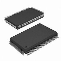
ISL51002CQZ-150 Intersil, ISL51002CQZ-150 Datasheet - Page 15

ISL51002CQZ-150
Manufacturer Part Number
ISL51002CQZ-150
Description
IC FRONT END 10BIT VID 128-MQFP
Manufacturer
Intersil
Datasheet
1.ISL51002CQZ-165.pdf
(32 pages)
Specifications of ISL51002CQZ-150
Number Of Bits
10
Number Of Channels
3
Power (watts)
1.2W
Voltage - Supply, Analog
1.8V, 3.3V
Voltage - Supply, Digital
1.8V, 3.3V
Package / Case
128-MQFP, 128-PQFP
Lead Free Status / RoHS Status
Lead free / RoHS Compliant
Available stocks
Company
Part Number
Manufacturer
Quantity
Price
Company:
Part Number:
ISL51002CQZ-150
Manufacturer:
Intersil
Quantity:
500
Register Listing
0x27
0x28
ADDRESS
ABLC Configuration, (0x40)
Output Format 1, (0x00)
(DEFAULT VALUE)
REGISTER
(Continued)
15
BITS
3:2
6:4
5:4
0
1
0
1
2
3
6
ABLC Disable
Offset DAC Range
ABLC Pixel Width
ABLC Bandwidth
Data Output Format
4:2:2 Order
4:2:2 Processing
8-bit Mode
Oversampling
RGB2YUV Color Space
Conversion Enable
FUNCTION NAME
ISL51002
0: ABLC on (default) - use 10-bit digital offset control.
1: ABLC off - use 10-bit offset DACs, bypass digital adder
0: ±1/2 ADC fullscale (1 LSB = 1 ADC LSBs)
1: ±1/4 ADC fullscale (1 LSB = 0.5 ADC LSBs)
Number of black pixels averaged every line for ABLC function
00: 16 pixels [default]
01: 32 pixels
10: 64 pixels
11: 128 pixels
ABLC Time constant (lines) = 2
000 = 32 lines
100 = 512 lines (default)
111 = 4096 lines
0: 4:4:4 (24-bit/30-bit output)
1: 4:2:2 (16-bit/20-bit output on G and R)
0: First pixel on R channel is U
1: First pixel on R channel is V
0: U, V fitered (high quality)
1: Odd U, V pixels dropped (lower quality)
0: All 10-bits of each channel active
1: 2 LSBs of each channel driven low (in 8-bit applications,
00: Normal operation (1x sampling)
01:2x oversampling, 2 samples averaged at ADC output
10:4x oversampling, 4 samples averaged at ADC output
11:8x oversampling, 8 samples averaged at ADC output
In Oversampling mode, the HTOTAL, DC Restore/ABLC Start,
DC Restore Width, and ABLC width values are automatically
multiplied by the oversampling ratio. The pixel clock is divided
by the oversampling ratio when the data is decimated.
Decimator is reset on trailing edge of HSYNC.
0: CSC Disabled
1: CSC Enabled
0x000 = -0x200 LSB offset, 0x3FF = +0x1FF LSB offset,
0x200 = 0x000 LSB offset
(add/subtract nothing, but keep same delay through
channel)
keep the LSBs from switching and generating noise)
Note: The data delay through the entire AFE is identical with
CSC on and CSC off.
DESCRIPTION
([5+6:4])
September 19, 2007
FN6164.2


