MCP3423-E/UN Microchip Technology, MCP3423-E/UN Datasheet - Page 17

MCP3423-E/UN
Manufacturer Part Number
MCP3423-E/UN
Description
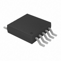
IC ADC 18BIT 3.75SPS 2CH 10-MSOP
Manufacturer
Microchip Technology
Specifications of MCP3423-E/UN
Data Interface
I²C, Serial
Number Of Bits
18
Sampling Rate (per Second)
3.75
Number Of Converters
1
Voltage Supply Source
Single Supply
Operating Temperature
-40°C ~ 125°C
Mounting Type
Surface Mount
Package / Case
10-TFSOP (0.118", 3.00mm Width)
Resolution (bits)
18bit
Sampling Rate
3.75SPS
Input Channel Type
Differential
Supply Voltage Range - Analog
2.7V To 5.5V
Supply Current
145µA
Lead Free Status / RoHS Status
Lead free / RoHS Compliant
For Use With
MCP3423EV - BOARD EVAL 18BIT 2CH ADC MCP3423
Lead Free Status / RoHS Status
Lead free / RoHS Compliant, Lead free / RoHS Compliant
Available stocks
Company
Part Number
Manufacturer
Quantity
Price
Part Number:
MCP3423-E/UN
Manufacturer:
MICROCHI
Quantity:
20 000
5.0
5.1
The user operates the device by setting up the device
configuration register using a write command (see
Figure
command (see
operates in two modes: (a) Continuous Conversion
Mode or (b) One-Shot Conversion Mode (single
conversion). This mode selection is made by setting
the O/C bit in the Configuration Register. Refer to
Section 5.2 “Configuration Register” for more
information.
5.1.1
The device performs a Continuous Conversion if the
O/C bit is set to logic “high”. Once the conversion is
completed, RDY bit is toggled to ‘0’ and the result is
placed at the output data register. The device immedi-
ately begins another conversion and overwrites the
output data register with the most recent result. The
device clears the data ready flag (RDY bit = 0) when
the conversion is completed. The device sets the ready
flag bit (RDY bit = 1), if the latest conversion result has
been read by the Master.
• When writing configuration register:
• When reading conversion data:
© 2008 Microchip Technology Inc.
- Setting RDY bit in continuous mode does not
- RDY bit = 0 means the latest conversion
- RDY bit = 1 means the conversion result is
affect anything.
result is ready.
not updated since the last reading. A new
conversion is under processing and the RDY
bit will be cleared when the new conversion
result is ready.
5-3) and reads the conversion data using a read
Operating Modes
USING THE DEVICES
CONTINUOUS CONVERSION
MODE (O/C BIT =
Figure 5-4
and
Figure
1
)
5-5). The device
5.1.2
Once the One-Shot Conversion (single conversion)
Mode is selected, the device performs only one conver-
sion, updates the output data register, clears the data
ready flag (RDY = 0), and then enters a low power
standby mode. A new One-Shot Conversion is started
again when the device receives a new write command
with RDY = 1.
• When writing configuration register:
• When reading conversion data:
This One-Shot Conversion Mode is highly recom-
mended for low power operating applications where the
conversion result is needed by request on demand.
During the low current standby mode, the device con-
sumes less than 1 µA maximum (or 300 nA typical).
For example, if the user collects 18 bit conversion data
once a second in One-Shot Conversion mode, the
device draws only about one fourth of its total operating
current. In this example, the device consumes approx-
imately 36 µA (135 µA / 3.75 SPS = 36 µA), if the
device performs only one conversion per second
(1 SPS) in 18-bit conversion mode with 3V power
supply.
- The RDY bit needs to be set to begin a new
- RDY bit = 0 means the latest conversion
- RDY bit = 1 means the conversion result is
conversion in one-shot mode.
result is ready.
not updated since the last reading. A new
conversion is under processing and the RDY
bit will be cleared when the new conversion is
done.
ONE-SHOT CONVERSION MODE
(O/C BIT =
MCP3422/3/4
0
)
DS22088B-page 17


