CS5340-CZZ Cirrus Logic Inc, CS5340-CZZ Datasheet
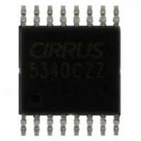
IC ADC AUD 101DB 200KHZ 16-TSSOP

CS5340-CZZ

Manufacturer Part Number
CS5340-CZZ
Description
IC ADC AUD 101DB 200KHZ 16-TSSOP
Manufacturer
Cirrus Logic Inc
Datasheets

Specifications of CS5340-CZZ

Package / Case
16-TSSOP
Number Of Converters
2
Number Of Bits
24
Sampling Rate (per Second)
200k
Data Interface
Serial
Voltage Supply Source
Single Supply
Operating Temperature
-10°C ~ 70°C
Mounting Type
Surface Mount
Conversion Rate
192 KSPS
Resolution
24 bit
Number Of Adc Inputs
2
Operating Supply Voltage
3.3 V or 5 V
Maximum Operating Temperature
+ 70 C
Minimum Operating Temperature
- 10 C
Mounting Style
SMD/SMT
Power Consumption
90 mW
Supply Voltage (max)
5.25 V
Supply Voltage (min)
3.1 V
Lead Free Status / RoHS Status
Lead free / RoHS Compliant
For Use With
598-1544 - BOARD EVAL FOR CS5340 STEREO ADC
Lead Free Status / Rohs Status
Lead free / RoHS Compliant
Other names
598-1081-5

Available stocks

Company
Part Number
Manufacturer
Quantity
Price
Part Number:
CS5340-CZZ
Manufacturer:
CIRRUS
Quantity:
306
Part Number:
CS5340-CZZ
Manufacturer:
EXCELITAS
Quantity:
3 556
Part Number:
CS5340-CZZ
Manufacturer:
CIRRUS
Quantity:
20 000
Company:
Part Number:
CS5340-CZZ
Quantity:
10
Company:
Part Number:
CS5340-CZZ
Quantity:
10
Company:
Part Number:
CS5340-CZZ
Quantity:
8 500
Part Number:
CS5340-CZZR
Manufacturer:
Cirrus Logic
Quantity:
4 000
Part Number:
CS5340-CZZR
Manufacturer:
CIRRUS/PBF
Quantity:
15
Part Number:
CS5340-CZZR
Manufacturer:
CIRRUS
Quantity:
20 000
Part Number:
CS5340-CZZR
0
Part Number:
CS5340-CZZR-
Manufacturer:
MS
Quantity:
10 000
1. Introduction
The CS5333 and CS5340 are complete stereo analog-to-digital converters for digital audio systems.
These converters perform sampling, analog-to-digital conversion and anti-alias filtering, generating 24-bit
values for both left and right channels. These small, low power converters are ideal for systems requiring
wide dynamic range and low noise such as set-top boxes, A/V receivers, DVD-karaoke players, DVD re-
corders, and automotive applications. The CS5333 is no longer recommended for new designs, and the
CS5340 is the suggested replacement.
This application note identifies the implementation differences between these two devices, including:
2. Key Specifications
Table 1 shows a comparison of the key specifications of these two devices, and Table 2 shows the pin
comparison between the CS5333 and the CS5340. Although these two devices are not pin compatible,
they are very similar in terms of overall functionality and feature set. The CS5340 achieves higher analog
performance and supports a wider range of output sample rates, including 192 kHz. This additional per-
formance is the main reason for the increased power consumption of the CS5340 relative to the CS5333.
http://www.cirrus.com
-
-
-
-
-
-
Key specifications
Pinout differences
Startup mode selections
System clocking
Input filter topology
Reference pin decoupling
Conversion
Dynamic Range (A-weighted)*
THD+N*
Analog Core Power Supply (VA)
Digital Core Power Supply (VD)
Digital Interface Power Supply (VL)
Maximum Power*
Maximum Sample Rate
Package
* All performance/power measurements taken with all supplies set to 3.3 V
CS5333 to CS5340 Conversion
Parameter
Table 1. Comparison of Key Specifications
Copyright © Cirrus Logic, Inc. 2004
by Kevin L Tretter
Powered from VA
(All Rights Reserved)
16-pin TSSOP
+1.8 to +3.3
+1.8 to +3.3
CS5333
100
-88
95
31
24
16-pin TSSOP
+3.3 to +5.0
+3.3 to +5.0
+1.8 to +5.0
CS5340
100
200
-95
24
98
Units
mW
AN249
Bits
kHz
dB
dB
V
V
V
AN249REV1
MAR ‘04
1

Related parts for CS5340-CZZ

CS5340-CZZ Summary of contents

Page 1

... The CS5340 achieves higher analog performance and supports a wider range of output sample rates, including 192 kHz. This additional per- formance is the main reason for the increased power consumption of the CS5340 relative to the CS5333. Parameter ...

Page 2

... The CS5333 and CS5340 are both available in a 16-pin TSSOP package. As can be seen from Table 2, all but three pins correlate directly in terms of functionality. These three pins account for a difference in operational mode selection and a separate voltage supply pin for the CS5340 digital core. ...

Page 3

... Typical Connection Diagrams Figures 1 and 2 illustrate the typical connection diagram for the CS5333 and CS5340 respectively. The analog and digital core of the CS5333 are powered from VA, which can be set from 1 3.3 V. The VL supply pin powers the digital interface logic from 1 3.3 V and can be set independently from VA. ...

Page 4

... Both the analog and digital cores can operate independently from 3 5.0 V. The VL pin of the CS5340 supplies the digital interface logic, supports a wide operating range from 1 5.0 V, and can be powered independently from the VA and VD power supplies. ...

Page 5

... CS5333. The CS5333 supports an MCLK/LRCK ratio of 256x, 384x, 512x, and 768x in Base Rate mode and 128x, 192x, 256x and 384x in High Rate mode. The CS5340 cannot support ratios of 192x, 384x, or 768x. See Table 4. Due to the auto-speed mode detect circuitry implemented in the CS5340, not all sam- ple rate ranges are supported in Slave mode ...

Page 6

... A passive input filter can be used with the CS5340, however, the full analog performance of the CS5340 will not be realized. Figure 5 illustrates a unity gain, passive input filter solution and the resulting distortion performance. Please note that in this case the dynamic range performance of the CS5340 will not be lim- ited by the input filter; only the distortion performance is affected. ...

Page 7

... B F -95 S -100 THD+N Input = -1 dBFS -105 20 50 Figure 5. CS5340 Passive Input Filter, Solution 1 VA 100 kΩ 10 µF 150 Ω 100 kΩ 100 200 500 Hz CS5340 AIN 2200 pF C0G AN249 10k 20k 7 ...

Page 8

... Some applications may require signal attenuation prior to the converter. The full-scale input voltage of the CS5340 will scale with the analog power supply voltage. For VA = 5.0 V, the full-scale input voltage is approximately 2.8 Vpp Vrms. Typical consumer audio line level outputs range from 1 Vrms. ...

Page 9

... The size of the decoupling capacitor on this reference pin will affect the low frequency distortion performance. The recommended solution for the CS5333 the FILT+ pin and analog ground. The recommended solution for the CS5340 is to use a 0.1 µ in parallel with capacitor for cost sensitive applications ...

Page 10

Revision Date 1 16 March 2004 Contacting Cirrus Logic Support For a complete listing of Direct Sales, Distributor, and Sales Representative contacts, visit the Cirrus Logic web site at: http://www.cirrus.com/ IMPORTANT NOTICE Cirrus Logic, Inc. and its subsidiaries ("Cirrus") believe ...

Related keywords