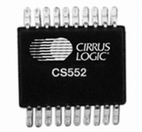
CS5523-ASZ Cirrus Logic Inc, CS5523-ASZ Datasheet - Page 43

CS5523-ASZ
Manufacturer Part Number
CS5523-ASZ
Description
IC ADC 16BIT SIG/DELT 24-SSOP
Manufacturer
Cirrus Logic Inc
Specifications of CS5523-ASZ
Number Of Converters
1
Package / Case
24-SSOP
Number Of Bits
16
Data Interface
Serial
Power Dissipation (max)
10mW
Voltage Supply Source
Analog and Digital
Operating Temperature
-40°C ~ 85°C
Mounting Type
Surface Mount
Number Of Adc Inputs
1
Architecture
Delta-Sigma
Conversion Rate
617 SPs
Resolution
24 bit
Input Type
Voltage
Interface Type
Serial (3-Wire)
Voltage Reference
2.5 V
Supply Voltage (max)
5 V
Supply Voltage (min)
25 mV
Maximum Power Dissipation
500 mW
Maximum Operating Temperature
+ 85 C
Mounting Style
SMD/SMT
Input Voltage
25 mV to 5 V
Minimum Operating Temperature
- 40 C
Lead Free Status / RoHS Status
Lead free / RoHS Compliant
Lead Free Status / RoHS Status
Lead free / RoHS Compliant, Lead free / RoHS Compliant
Other names
598-1105-5
Available stocks
Company
Part Number
Manufacturer
Quantity
Price
Part Number:
CS5523-ASZ
Manufacturer:
CIRRUSLOGIC
Quantity:
20 000
2.8 Power Supply Arrangements
The CS5521/22/23/24/28 A/D converters are de-
signed to operate from a single +5 V analog supply
and a single +5 V or +3 V digital supply. A -2.1 V
supply is usually generated from the charge pump
drive to provide power to the instrumentation am-
plifier’s NBV (negative bias voltage) pin.
Figure 21 illustrates the CS5522 connected with a
+5 V analog supply and with the external compo-
nents required for the charge pump drive. This en-
ables the CS5522 to measure ground-referenced
signals with magnitudes down to ±100 mV.
Figure 22 illustrates the CS5522 connected to mea-
sure ground-referenced unipolar signals of a posi-
tive polarity using the 1 V, 2.5 V, and 5 V ranges
DS317F4
L M 3 3 4
A b s o lu te
C u rre n t
R e fe re n c e
A n a lo g
S u p p ly
+ 5 V
Figure 21. CS5522 Configured to use on-chip charge pump to supply NBV
C o ld J u n c tio n
U p to ± 1 0 0 m V In p u t
+ 5 V
2 .5 V
V -
V +
3 0 1 Ω
R
1 0 k Ω
1 0 k Ω
0 .1 µ F
4 9 9 Ω
B A V 1 9 9
0 .1 µ F
2 0
1 9
1 8
1 7
1 6
3
4
1
6
B A T 8 5
V R E F +
V R E F -
A IN 1 +
A IN 1 -
A G N D
A IN 2 +
A IN 2 -
A 1
A 0
V A +
N B V
2
5
1 N 4 1 4 8
+
on the converter. For the 25 mV, 55 mV, and
100 mV ranges, the signals being digitized must
have a common mode between +1.85 to +2.65 V
(NBV = 0 V).
Although CS5521/22/23/24/28 are optimized for
the measurement of thermocouple outputs, they are
also well suited for the measurement of ratiometric
bridge transducer outputs. Figure 23 illustrates the
CS5522 connected to measure the output of a rati-
ometric differential bridge transducer while operat-
ing from a single +5 V supply. Bridge outputs may
range from 5 mV to 400 mV. See “Digital Gain
Scaling” on page 45 section about manipulating the
gain register to achieve optimum gain scaling.
1 0 µ F
C S5522
1 0 Ω
C P D
7
V D +
1 N 4 1 4 8
0 .033 µ F
X O U T
D G N D
S C L K
S D O
1 4
X IN
S D I
C S
1 3
1 1
10
9
1 5
8
1 2
L o g ic O u tp u ts :
A 0 - A 1 S w itc h fro m
V A + to A G N D .
C h a rg e -p u m p n e tw o rk
fo r V D + = 5 V o n ly a n d
X IN = 3 2 .7 6 8 k H z .
3 2 .7 6 8 ~ 1 0 0 k H z
CS5521/22/23/24/28
In te rfa ce
O p tio n a l
S o u rce
S e ria l
C lo c k
D a ta
0 .1 µ F
43


