281792-4 TE Connectivity, 281792-4 Datasheet - Page 22
281792-4
Manufacturer Part Number
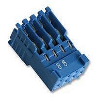
281792-4
Description
PLUG HE14 IDC 180 2X4 P AWG 28-26
Manufacturer
TE Connectivity
Series
HE14r
Datasheet
1.525421-5.pdf
(23 pages)
Specifications of 281792-4
Connector Type
Wire To Board
Contact Termination
IDC / IDT
Gender
Receptacle
No. Of Contacts
8
No. Of Rows
2
Pitch Spacing
2.54mm
Contact Plating
Tin
Rohs Compliant
Yes
Product Type
Connector
Termination Method To Wire/cable
Crimp, Insulation Displacement Crimp (IDC)
Mating Connector Lock
Without
Wire Insulation Diameter (mm [in])
1.00 [0.039]
Connector Series
HE13 / HE14
Keyed
No
Centerline (mm [in])
2.54 [0.100]
Row-to-row Spacing (mm [in])
2.54 [0.100]
Number Of Positions
8
Number Of Rows
2
Wire Range (mm [awg])
0.08-0.15² [28-26]
Contact Type
Socket
Contact Plating, Mating Area, Material
Tin
Contact Base Material
Phosphor Bronze
Connector Style
Receptacle
Mating Alignment
Without
Housing Color
Blue
Ul Flammability Rating
UL 94V-0
Housing Material
PBT - GF
Rohs/elv Compliance
RoHS compliant, ELV compliant
Lead Free Solder Processes
Not relevant for lead free process
Rohs/elv Compliance History
Always was RoHS compliant
Applies To
Wire/Cable
Packaging Method
Loose Piece


Tyco Electronics France SAS, B.P. 30039 95301 CERGY-PONTOISE Cedex Tél. 01 34 20 88 88 Fax 01 34 20 86 00
This document, managed by Tyco Electronics France, is archived in the Startec database.
A printout cannot be considered as a controlled document.
1. SCOPE
This document provides the instructions for the termination of IDC plugs, 90° wire exit, HE13- HE14 series, meeting the
requirements of international standard IEC 603-8.
2. TERMINATION
Every family of connectors is dedicated to a single wire gauge (see list on the last page of this document).
The accepted range varies from 0.08 mm
Other usages are not recommended and should be evaluated on a case by case basis.
2.2. Application tooling
The termination can be acccomplished by hand-tools or more productive application tooling. It can be done conductor
by conductor or simultaneously.
3. TERMINOLOGY
4. WIRING TYPES
The connectors can be placed at the end of the lead or in a daisy chain configuration (see figure 2) .
Care should be taken not to stress the connector when the wires are cut.
2.1. The connectors above are to be terminated to discrete wires type KY 30 (7 strands-PVC jacket) per French
standard NF C 93-521 or ribbon cable with a 2.54 mm of the same characteristics.
Drawing by : A. CAMEL
IDC PLUGS 90° HE13-HE14 SERIES-IEC 603-8
Date : April 1987
2
-AWG 28 (KY 30-02) to 0.22 mm
locking lances
Figure 1
Figure 2
Approved by : Y. PETRONIN
2
- AWG24 (KY 30-04).
wire
housing
contact
Application specification
114-15030
Date : April 1987
21 June 07 Rev. B
1 to 2
Related parts for 281792-4
Image
Part Number
Description
Manufacturer
Datasheet
Request
R

Part Number:
Description:
SOCKET IDT, 2ROW, 16WAY
Manufacturer:
TE Connectivity
Datasheet:

Part Number:
Description:
SOCKET IDT, 2ROW, 10WAY
Manufacturer:
TE Connectivity
Datasheet:

Part Number:
Description:
Manufacturer:
TE Connectivity
Datasheet:
Part Number:
Description:
Manufacturer:
TE Connectivity
Datasheet:

Part Number:
Description:
WIRE-BOARD CONN RECEPTACLE, 6POS, 2.54MM
Manufacturer:
TE Connectivity
Datasheet:

Part Number:
Description:
High Speed / Modular Connectors 30P HEADER ASSY
Manufacturer:
TE Connectivity
Datasheet:

Part Number:
Description:
High Speed / Modular Connectors REC 6X005P R/A LT B-PLANE HS3
Manufacturer:
TE Connectivity
Datasheet:

Part Number:
Description:
High Speed / Modular Connectors 2MM HM RCPT 50P R/A AU
Manufacturer:
TE Connectivity
Datasheet:

Part Number:
Description:
High Speed / Modular Connectors 2MM HM RCPT 50P R/A AU
Manufacturer:
TE Connectivity
Datasheet:


Part Number:
Description:
Manufacturer:
TE Connectivity
Datasheet:


Part Number:
Description:
Manufacturer:
TE Connectivity
Datasheet:

Part Number:
Description:
Manufacturer:
TE Connectivity
Datasheet:

Part Number:
Description:
Manufacturer:
TE Connectivity
Datasheet: