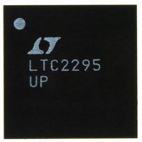
LTC2295IUP#PBF Linear Technology, LTC2295IUP#PBF Datasheet - Page 3

LTC2295IUP#PBF
Manufacturer Part Number
LTC2295IUP#PBF
Description
IC ADC DUAL 14BIT 10MSPS 64QFN
Manufacturer
Linear Technology
Datasheet
1.LTC2295IUPPBF.pdf
(24 pages)
Specifications of LTC2295IUP#PBF
Number Of Bits
14
Sampling Rate (per Second)
10M
Data Interface
Parallel
Number Of Converters
2
Power Dissipation (max)
138mW
Voltage Supply Source
Single Supply
Operating Temperature
-40°C ~ 85°C
Mounting Type
Surface Mount
Package / Case
64-WFQFN, Exposed Pad
Lead Free Status / RoHS Status
Lead free / RoHS Compliant
Available stocks
Company
Part Number
Manufacturer
Quantity
Price
DY A IC ACCURACY
A ALOG I PUT
otherwise specifications are at T
SYMBOL
SNR
SFDR
SFDR
S/(N+D)
I
SYMBOL
V
V
I
I
I
t
t
CMRR
specifications are at T
MD
IN
SENSE
MODE
AP
JITTER
IN
IN,CM
U
U W
Spurious Free Dynamic Range
2nd or 3rd Harmonic
PARAMETER
Analog Input Range (A
Analog Input Common Mode (A
Analog Input Leakage Current
SENSEA, SENSEB Input Leakage
MODE Input Leakage Current
Sample-and-Hold Acquisition Delay Time
Sample-and-Hold Acquisition Delay Time Jitter
Analog Input Common Mode Rejection Ratio
Full Power Bandwidth
PARAMETER
Signal-to-Noise Ratio
Spurious Free Dynamic Range
4th Harmonic or Higher
Signal-to-Noise Plus Distortion Ratio
Intermodulation Distortion
Crosstalk
U
A
= 25°C. (Note 4)
The
A
= 25°C. A
●
IN
denotes the specifications which apply over the full operating temperature range, otherwise
+
–A
The
IN
IN
–
)
IN
●
= –1dBFS. (Note 4)
+
+A
denotes the specifications which apply over the full operating temperature range,
IN
–
)/2
CONDITIONS
5MHz Input
70MHz Input
5MHz Input
70MHz Input
5MHz Input
70MHz Input
5MHz Input
70MHz Input
f
f
CONDITIONS
2.7V < V
Differential Input (Note 7)
Single Ended Input (Note 7)
0V < A
0V < SENSEA, SENSEB < 1V
0V < MODE < V
Figure 8 Test Circuit
IN
IN
= 4.3MHz, 4.6MHz
= 5MHz
IN
DD
+
, A
< 3.4V (Note 7)
IN
–
DD
< V
DD
●
●
●
●
●
●
●
●
●
●
MIN
71.6
MIN
0.5
75
80
71
–1
–3
–3
1
±0.5 to ±1
–110
74.4
73.2
74.4
73.1
TYP
TYP
575
1.5
1.5
0.2
90
85
90
90
90
80
0
LTC2295
MAX
MAX
1.9
2
1
3
3
UNITS
UNITS
ps
2295fa
3
MHz
RMS
dB
dB
dB
dB
dB
dB
dB
dB
dB
dB
µA
µA
µA
dB
ns
V
V
V


