AD574AKD Analog Devices Inc, AD574AKD Datasheet - Page 11
AD574AKD
Manufacturer Part Number
AD574AKD
Description
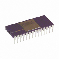
IC ADC 12BIT W/REF 28-CDIP
Manufacturer
Analog Devices Inc
Specifications of AD574AKD
Data Interface
Parallel
Rohs Status
RoHS non-compliant
Number Of Bits
12
Sampling Rate (per Second)
28.6k
Number Of Converters
1
Power Dissipation (max)
725mW
Voltage Supply Source
Dual ±
Operating Temperature
0°C ~ 70°C
Mounting Type
Through Hole
Package / Case
28-CDIP (0.600", 15.24mm)
Resolution (bits)
12bit
Input Channel Type
Differential
Supply Voltage Range - Analogue
± 11.4V To ± 16.5V
Supply Voltage Range - Digital
4.5V To 5.5V
Supply Current
30mA
No.
RoHS Compliant
Digital Ic Case Style
DIP
No. Of Pins
28
Rohs Compliant
No
Lead Free Status / RoHS Status
Available stocks
Company
Part Number
Manufacturer
Quantity
Price
Company:

Part Number:
AD574AKD
Manufacturer:
INTERSIL
Quantity:
210
Company:
Part Number:
AD574AKD
Manufacturer:
AD
Quantity:
3 909
Company:
Part Number:
AD574AKD
Manufacturer:
AD
Quantity:
3 909
Part Number:
AD574AKD
Manufacturer:
ADI/亚德诺
Quantity:
20 000
Company:
Part Number:
AD574AKD/AJD
Manufacturer:
MOT
Quantity:
4


REV. B
IBM PC Interface
The AD574A appears in Figure 17 interfaced to the 4 MHz
8088 processor of an IBM PC. Since the device resides in I/O
space, its address is decoded from only the lower ten address
lines and must be gated with AEN (active low) to mask out in-
ternal DMA cycles which use the same I/O address space. This
active low signal is applied to CS. IOR and IOW are used to
initiate the conversion and read, and are gated together to drive
the chip enable, CE. Because the data bus width is limited to
8 bits, the AD574A data resides in two adjacent addresses
selected by A0.
Figure 17. IBM PC—AD574A Interface
Figure 15. Z80—AD574A Interface
Figure 16. Wait State Generator
–11–
Note: Due to the large number of options that may be installed
in the PC, the I/O bus loading should be limited to one Schottky
TTL load. Therefore, a buffer/driver should be used when inter-
facing more than two AD574As to the I/O bus.
8086 Interface
The data mode select pin (12/8) of the AD574A should be con-
nected to V
possible bus contention, a demultiplexed and buffered address/
data bus is recommended. In the cases where the 8-bit short
conversion cycle is not used, A0 should be tied to digital com-
mon. Figure 18 shows a typical 8086 configuration.
For clock speeds greater than 4 MHz wait state insertion similar
to Figure 16 is recommended to ensure sufficient CE and R/C
pulse duration.
The AD574A can also be interfaced in a stand-alone mode (see
Figure 13). A low going pulse derived from the 8086’s WR sig-
nal logically ORed with a low address decode starts the conver-
sion. At the end of the conversion, STS clocks the data into the
three-state latches.
68000 Interface
The AD574, when configured in the stand-alone mode, will eas-
ily interface to the 4 MHz version of the 68000 microprocessor.
The 68000 R/W signal combined with a low address decode ini-
tiates conversion. The UDS or LDS signal, with the decoded
address, generates the DTACK input to the processor, latching
in the AD574A’s data. Figure 19 illustrates this configuration.
Figure 18. 8086—AD574A with Buffered Bus lnterface
LOGIC
Figure 19. 68000—AD574A Interface
to provide a 12-bit data output. To prevent
AD574A
Related parts for AD574AKD
Image
Part Number
Description
Manufacturer
Datasheet
Request
R

Part Number:
Description:
±1.7g Dual-Axis IMEMS Accelerometer Evaluation Board
Manufacturer:
Analog Devices Inc
Datasheet:

Part Number:
Description:
Inertial Sensor Evaluation System
Manufacturer:
Analog Devices Inc
Datasheet:
Part Number:
Description:
Manufacturer:
Analog Devices Inc
Datasheet:
Part Number:
Description:
Manufacturer:
Analog Devices Inc
Datasheet:
Part Number:
Description:
Manufacturer:
Analog Devices Inc
Datasheet:
Part Number:
Description:
Manufacturer:
Analog Devices Inc
Datasheet:
Part Number:
Description:
Manufacturer:
Analog Devices Inc
Datasheet:
Part Number:
Description:
Manufacturer:
Analog Devices Inc
Datasheet:
Part Number:
Description:
Manufacturer:
Analog Devices Inc
Datasheet:
Part Number:
Description:
Manufacturer:
Analog Devices Inc
Datasheet:
Part Number:
Description:
Manufacturer:
Analog Devices Inc
Datasheet:
Part Number:
Description:
Manufacturer:
Analog Devices Inc
Datasheet:
Part Number:
Description:
Manufacturer:
Analog Devices Inc
Datasheet: