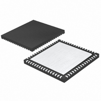
LTC2216IUP#PBF Linear Technology, LTC2216IUP#PBF Datasheet - Page 29

LTC2216IUP#PBF
Manufacturer Part Number
LTC2216IUP#PBF
Description
IC ADC 16BIT 80MSPS 64-QFN
Manufacturer
Linear Technology
Datasheet
1.LTC2216CUPPBF.pdf
(36 pages)
Specifications of LTC2216IUP#PBF
Number Of Bits
16
Sampling Rate (per Second)
80M
Data Interface
Parallel
Number Of Converters
1
Power Dissipation (max)
1.52W
Voltage Supply Source
Single Supply
Operating Temperature
-40°C ~ 85°C
Mounting Type
Surface Mount
Package / Case
64-WFQFN, Exposed Pad
Lead Free Status / RoHS Status
Lead free / RoHS Compliant
Available stocks
Company
Part Number
Manufacturer
Quantity
Price
APPLICATIONS INFORMATION
PC BOARD
Figure 15. Descrambling a Scrambled Digital Output
LTC2216/
LTC2215
ANALOG
INPUT
D15 D0
D14 D0
CLKOUT
D2 D0
D1 D0
AIN
AIN
D0
OF
+
–
Figure 16. Functional Equivalent Block Diagram of Internal Dither Circuit
LTC2216/LTC2215
CLOCK/DUTY
ENC
CONTROL
FPGA
AMP
S/H
CYCLE
+
ENC
–
•
•
•
D15
D14
D2
D1
D0
22165 F15
PRECISION
PIPELINED
ADC CORE
16-BIT
DAC
Internal Dither
The LTC2216/LTC2215 is a 16-bit ADC with a very linear
transfer function; however, at low input levels even slight
imperfections in the transfer function will result in unwanted
tones. Small errors in the transfer function are usually a
result of ADC element mismatches. An optional internal
dither mode can be enabled to randomize the input location
on the ADC transfer curve, resulting in improved SFDR
for low signal levels.
As shown in Figure 16, the output of the sample-and-hold
amplifi er is summed with the output of a dither DAC. The
dither DAC is driven by a long sequence pseudo-random
number generator; the random number fed to the dither DAC
is also subtracted from the ADC result. If the dither DAC
is precisely calibrated to the ADC, very little of the dither
signal will be seen at the output. The dither signal that does
leak through will appear as white noise. The dither DAC is
calibrated to result in typically less than 0.5dB elevation
in the noise fl oor of the ADC, as compared to the noise
fl oor with dither off when a suitable input termination is
provided (see Demo Board schematic DC996B).
SUMMATION
DIGITAL
PSEUDO-RANDOM
HIGH = DITHER ON
LOW = DITHER OFF
MULTIBIT DEEP
LTC2216/LTC2215
DITHER ENABLE
GENERATOR
NUMBER
DRIVERS
OUTPUT
DITH
22165 F16
CLKOUT
D15
D0
OF
•
•
•
29
22165f


