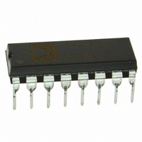
AD7715ANZ-3 Analog Devices Inc, AD7715ANZ-3 Datasheet - Page 18

AD7715ANZ-3
Manufacturer Part Number
AD7715ANZ-3
Description
IC ADC 16BIT SIGMA-DELTA 16DIP
Manufacturer
Analog Devices Inc
Specifications of AD7715ANZ-3
Data Interface
DSP, MICROWIRE™, QSPI™, Serial, SPI™
Number Of Bits
16
Sampling Rate (per Second)
500
Number Of Converters
1
Power Dissipation (max)
9.5mW
Voltage Supply Source
Analog and Digital
Operating Temperature
-40°C ~ 85°C
Mounting Type
Through Hole
Package / Case
16-DIP (0.300", 7.62mm)
Resolution (bits)
16bit
Input Channel Type
Differential
Supply Voltage Range - Analogue
3V To 3.6V
Supply Voltage Range - Digital
3V To 5.25V
Supply Current
600µA
No. Of
RoHS Compliant
Sampling Rate
19.2kSPS
Rohs Compliant
Yes
Lead Free Status / RoHS Status
Lead free / RoHS Compliant
For Use With
EVAL-AD7715-3EBZ - BOARD EVALUATION FOR AD7715
Lead Free Status / RoHS Status
Lead free / RoHS Compliant
Available stocks
Company
Part Number
Manufacturer
Quantity
Price
Company:
Part Number:
AD7715ANZ-3
Manufacturer:
INFINEON
Quantity:
12
Part Number:
AD7715ANZ-3
Manufacturer:
ADI/亚德诺
Quantity:
20 000
AD7715
CALIBRATION SEQUENCES
The AD7715 contains a number of calibration options as
outlined in Table 13. Table 23 summarizes the calibration types,
the operations involved and the duration of the operations.
There are two methods of determining the end of calibration.
The first is to monitor when DRDY returns low at the end of
the sequence. DRDY not only indicates when the sequence is
complete but also that the part has a valid new sample in its
data register. This valid new sample is the result of a normal
conversion which follows the calibration sequence. The second
method of determining when calibration is complete is to
monitor the MD1 and MD0 bits of the setup register. When
Table 23. Calibration Sequences
Calibration Type
Self Calibration
ZS System Calibration
FS System Calibration
MD1, MD0
0, 1
1, 0
1, 1
Calibration Sequence
Internal ZS Cal @ Selected Gain +
Internal FS Cal @ Selected Gain
ZS Cal on AIN @ Selected Gain
FS Cal on AIN @ Selected Gain
Rev. D | Page 18 of 40
these bits return to 0, 0 following a calibration command, it
indicates that the calibration sequence is complete. This method
does not give any indication of there being a valid new result in
the data register. However, it gives an earlier indication than
DRDY that calibration is complete. The duration to when the
mode bits (MD1 and MD0) return to 0, 0 represents the
duration of the calibration carried out. The sequence to when
DRDY goes low also includes a normal conversion and a
pipeline delay, t
conversion. t
methods is given in
Duration to Mode Bits
3 × 1/Output Rate
3 × 1/Output Rate
6 × 1/Output Rate
P
will never exceed 2000 × t
P
, to correctly scale the results of this first
Table 23
.
Duration to DRDY
9 ×1/Output Rate + t
4 × 1/Output Rate + t
4 × 1/Output Rate + t
CLK IN
. The time for both
P
P
P


