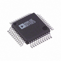
AD7864ASZ-2 Analog Devices Inc, AD7864ASZ-2 Datasheet - Page 2

AD7864ASZ-2
Manufacturer Part Number
AD7864ASZ-2
Description
IC ADC 14BIT DUAL 4CHAN 44-MQFP
Manufacturer
Analog Devices Inc
Datasheet
1.AD7864ASZ-1.pdf
(28 pages)
Specifications of AD7864ASZ-2
Data Interface
Parallel
Number Of Bits
12
Sampling Rate (per Second)
520k
Number Of Converters
1
Power Dissipation (max)
120mW
Voltage Supply Source
Analog and Digital
Operating Temperature
-40°C ~ 85°C
Mounting Type
Surface Mount
Package / Case
44-MQFP, 44-PQFP
Resolution (bits)
12bit
Sampling Rate
500kSPS
Input Channel Type
Single Ended
Supply Voltage Range - Analog
4.75V To 5.25V
Supply Current
24mA
Digital Ic Case Style
QFP
Number Of Elements
1
Resolution
12Bit
Architecture
SAR
Sample Rate
520KSPS
Input Polarity
Unipolar
Input Type
Voltage
Rated Input Volt
2.5/5V
Differential Input
No
Power Supply Requirement
Analog and Digital
Single Supply Voltage (typ)
5V
Single Supply Voltage (min)
4.75V
Single Supply Voltage (max)
5.25V
Dual Supply Voltage (typ)
Not RequiredV
Dual Supply Voltage (min)
Not RequiredV
Dual Supply Voltage (max)
Not RequiredV
Power Dissipation
120mW
Differential Linearity Error
±0.9LSB
Integral Nonlinearity Error
±1LSB
Operating Temp Range
-40C to 85C
Operating Temperature Classification
Industrial
Mounting
Surface Mount
Pin Count
44
Package Type
MQFP
Input Signal Type
Single-Ended
Lead Free Status / RoHS Status
Lead free / RoHS Compliant
Lead Free Status / RoHS Status
Lead free / RoHS Compliant, Lead free / RoHS Compliant
Available stocks
Company
Part Number
Manufacturer
Quantity
Price
Company:
Part Number:
AD7864ASZ-2
Manufacturer:
Analog Devices Inc
Quantity:
135
Company:
Part Number:
AD7864ASZ-2
Manufacturer:
Analog Devices Inc
Quantity:
10 000
Part Number:
AD7864ASZ-2
Manufacturer:
ADI/亚德诺
Quantity:
20 000
Company:
Part Number:
AD7864ASZ-2REEL
Manufacturer:
Analog Devices Inc
Quantity:
10 000
AD7864
TABLE OF CONTENTS
Features .............................................................................................. 1
Applications ....................................................................................... 1
General Description ......................................................................... 1
Functional Block Diagram .............................................................. 1
Product Highlights ........................................................................... 1
Revision History ............................................................................... 2
Specifications ..................................................................................... 3
Absolute Maximum Ratings ............................................................ 6
Pin Configuration and Function Descriptions ............................. 7
Terminology ...................................................................................... 9
Theory of Operation ...................................................................... 11
Circuit Description ......................................................................... 13
Selecting a Conversion Sequence ................................................. 15
REVISION HISTORY
2/09—Rev. C to Rev. D
Change to t
2/09—Rev. B to Rev. C
Updated Format .................................................................. Universal
Changes to t
Changes to Figure 15 ...................................................................... 20
Changes to AD7864 to MC68HC000 Interface Section ............ 24
Changes to Figure 25 ...................................................................... 24
Updated Outline Dimensions ....................................................... 29
Changes to Ordering Guide .......................................................... 29
Timing Characteristics ................................................................ 5
ESD Caution .................................................................................. 6
Converter Details ........................................................................ 11
Analog Input ............................................................................... 13
Timing and Control ................................................................... 15
Using an External Clock ............................................................ 17
2
5
Parameter, Table 2 ...................................................... 5
Timing Parameter, Table 2....................................... 5
Rev. D | Page 2 of 28
Offset and Full-Scale Adjustment ................................................ 20
Dynamic Specifications ................................................................. 21
Microprocessor Interfacing ........................................................... 24
Outline Dimensions ....................................................................... 27
3/04—Rev. A to Rev. B.
Changes to Specifications and to Footnote 4 ................................. 2
Changes to Timing Characteristics Footnote 1 ............................. 4
Addition to Absolute Maximum Ratings ....................................... 5
Changes to Ordering Guide ............................................................. 5
Changes to Figure 7 ......................................................................... 11
Changes to Figure 11 ...................................................................... 13
Updated Outline Dimensions ....................................................... 19
Added Revision History ................................................................ 20
Updated Publication Code ............................................................ 20
Standby Mode Operation .......................................................... 18
Accessing the Output Data Registers ....................................... 18
Positive Full-Scale Adjust .......................................................... 20
Negative Full-Scale Adjust ......................................................... 20
Signal-to-Noise Ratio (SNR)..................................................... 21
Effective Number of Bits ........................................................... 21
Intermodulation Distortion ...................................................... 21
AC Linearity Plots ...................................................................... 22
Measuring Aperture Jitter .......................................................... 22
AD7864 to ADSP-2100/ADSP-2101/ADSP-2102 Interface . 24
AD7864 to TMS320C5x Interface ............................................ 24
AD7864 to MC68HC000 Interface .......................................... 24
Vector Motor Control ................................................................ 25
Multiple AD7864s in A System ................................................. 26
Ordering Guide .......................................................................... 27


