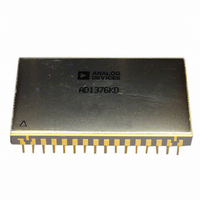
ADADC80-12 Analog Devices Inc, ADADC80-12 Datasheet - Page 13

ADADC80-12
Manufacturer Part Number
ADADC80-12
Description
IC ADC 12-BIT INTEGRATED 32-CDIP
Manufacturer
Analog Devices Inc
Datasheet
1.ADADC80-12.pdf
(16 pages)
Specifications of ADADC80-12
Data Interface
Parallel
Rohs Status
RoHS non-compliant
Number Of Bits
12
Sampling Rate (per Second)
40k
Number Of Converters
1
Power Dissipation (max)
800mW
Voltage Supply Source
Analog and Digital, Dual ±
Operating Temperature
-25°C ~ 85°C
Mounting Type
Through Hole
Package / Case
32-CDIP (0.900", 22.86mm)
Resolution (bits)
12bit
Input Channel Type
Single Ended
Supply Current
70mA
Digital Ic Case Style
DIP
No. Of Pins
32
Operating Temperature Range
-25°C To +85°C
Number Of Elements
1
Resolution
12Bit
Architecture
SAR
Input Polarity
Unipolar/Bipolar
Input Type
Voltage
Rated Input Volt
5/10/±2.5/±5/±10V
Differential Input
No
Power Supply Requirement
Dual
Single Supply Voltage (typ)
Not RequiredV
Single Supply Voltage (min)
Not RequiredV
Single Supply Voltage (max)
Not RequiredV
Dual Supply Voltage (typ)
±15/5V
Dual Supply Voltage (min)
±14/4.75V
Dual Supply Voltage (max)
±16/5.25V
Differential Linearity Error
±0.5LSB(Typ)
Integral Nonlinearity Error
±0.012%FSR
Operating Temp Range
-25C to 85C
Operating Temperature Classification
Commercial
Mounting
Through Hole
Pin Count
32
Package Type
SBCDIP
Input Signal Type
Single-Ended
Lead Free Status / Rohs Status
Not Compliant
Available stocks
Company
Part Number
Manufacturer
Quantity
Price
Part Number:
ADADC80-12
Manufacturer:
AD
Quantity:
20 000
CONTROL MODES
The timing sequence of the ADADC80 allows the device to be
easily operated in a variety of systems with different control
modes. The most common control modes are illustrated in
Figure 16, Figure 17, and Figure 18.
Conversion Initiated by the Rising Edge of Convert Command
COMMAND
CONVERT
Figure 16. Internal Clock—Normal Operating Mode,
(Internal Clock Runs Only During Conversion)
18
CONVERT
START
ADADC80
EXTERNAL
CLOCK IN
INHIBIT
SHORT
CLOCK
CYCLE
BIT 11
28
21
20
19
10-BIT
OPERATION
12-BIT
OPERATION
5V
Rev. E | Page 13 of 16
Figure 17. Continuation Conversion with External Clock Conversion Initiated
Figure 18. Continuous External Clock Conversion Initiated by Rising Edge of
EXTERNAL
CLOCK
CONV
COMM
Convert Command (Convert Command Must Be Synchronized with Clock)
ERT
AND
EXTERNAL
COMMON
DIGITAL
CLOCK
by 14th Clock Pulse (Clock Runs Continuously)
19
18
EXTERNAL
CLOCK IN
CONVERT
START
ADADC80
19
22
18
EXTERNAL
CLOCK IN
STATUS
CONVERT
START
CLOCK
INHIBIT
SHORT
CYCLE
ADADC80
BIT 11
28
21
20
INHIBIT
SHORT
CLOCK
CYCLE
BIT 11
DIGITAL
COMMON
28
21
20
10-BIT
OPERATION
12-BIT
OPERATION
ADADC80
5V
DIGITAL
COMMON
10-BIT
OPERATION
12-BIT
OPERATION
5V


