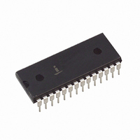
HI3-7159A-5 Intersil, HI3-7159A-5 Datasheet - Page 9

HI3-7159A-5
Manufacturer Part Number
HI3-7159A-5
Description
CONV A/D 5.5 DIGITIC MPU 28-DIP
Manufacturer
Intersil
Datasheet
1.HI3-7159A-5.pdf
(14 pages)
Specifications of HI3-7159A-5
Number Of Bits
8
Sampling Rate (per Second)
200k
Data Interface
Serial, Parallel
Number Of Converters
1
Voltage Supply Source
Analog and Digital, Dual ±
Operating Temperature
0°C ~ 70°C
Mounting Type
Through Hole
Package / Case
28-DIP (0.600", 15.24mm)
Lead Free Status / RoHS Status
Contains lead / RoHS non-compliant
Available stocks
Company
Part Number
Manufacturer
Quantity
Price
Single Conversion Mode
The suggested algorithm for reading the HI-7159A in its
single conversion mode of operation is shown in Figure 5.
Essentially it consists of initiating a conversion, waiting until
the conversion is complete, and then reading the results.
Since no further conversions take place, the data may be
read out at any time and at any speed. This is the most
straightforward method of reading the HI-7159A.
(
Digit Pair 0, 1
Digit Pair 2, 3
Digit Pair 4, 5
Digits 0 - 4
Digit 5
†
(
D7
= Reserved)
†
0
)
D7
0
DIGIT BYTE
DIGIT BYTE
No Update
Updated
UPDATE STATUS
CONVERTER
D6
0
(RESERVED)
TABLE 9. DIGIT BYTE FORMAT, PARALLEL AND SERIAL MODE 1 (RECEIVED FROM HI-7159A)
D6
TABLE 10. DIGIT BYTE FORMAT, SERIAL MODE 2 (RECEIVED FROM HI-7159A)
0
1
(1 = POS)
Polarity
MSB1
MSB3
TABLE 7. REQUEST BYTE FORMAT, SERIAL MODE 2 (SENT TO HI-7159A)
9
D5
D7
D7
0
0
0
(
D5
TABLE 8. STATUS BYTE FORMAT (RECEIVED FROM HI-7159A)
†
0
)
Single
Continuous
Overrange
(1 = OR)
D4
D6
0
0
0
CONTINUITY
D6
Digit 0
Digit 1
Digit 2
Digit 3
Digit 4
Digit 5
Converter Status
D5
1
1
MSB5
D4
HI-7159A
0
1
D5
5
4
1
1
RESOLUTION
/
/
2
2
D4
1
1
Continuous Conversion Mode
Once a command byte is sent to the HI-7159A initiating the
continuous conversion mode, the output data registers will be
updated continuously after every conversion. This makes
obtaining a valid reading more difficult, since the possibility
exists that the current data could be overwritten by a new
conversion before all the digit bytes are read. To prevent this,
the status byte should be read before and after the data is
read from the converter, to ensure that the converter has not
updated during the reads. This is demonstrated in Figure 6.
LSB1
LSB3
LSB5
D4
BYTE REQUEST
D3
1
0
D3
0
0
0
0
1
1
1
(1 = POS)
Polarity
MSB
Comp
Uncomp
Error
D3
MSB0
MSB2
MSB4
D3
CONVERSION TYPE
D2
0
0
1
1
0
0
1
Overrange
(1 = OR)
D2
D2
D2
1
1
0
D1
0
1
0
1
0
1
0
D1
1
0
1
MSB
LSB
D1
D1
No
Yes
REQUEST BIT
PARITY
ERROR
D0
1
LSB0
LSB2
LSB4
LSB
D0
D0
D0
0
1


