HI3-DAC80V-5 Intersil, HI3-DAC80V-5 Datasheet
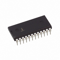
CONV D/A 12BIT OUTPUT AMP 24PDIP

HI3-DAC80V-5

Manufacturer Part Number
HI3-DAC80V-5
Description
CONV D/A 12BIT OUTPUT AMP 24PDIP
Manufacturer
Intersil
Datasheet

Specifications of HI3-DAC80V-5

Settling Time
1.5µs
Number Of Bits
12
Data Interface
Parallel
Number Of Converters
1
Voltage Supply Source
Dual ±
Operating Temperature
0°C ~ 75°C
Mounting Type
Through Hole
Package / Case
24-DIP (0.600", 15.24mm)
Lead Free Status / RoHS Status
Contains lead / RoHS non-compliant
Power Dissipation (max)
-

Available stocks

Company
Part Number
Manufacturer
Quantity
Price
Part Number:
HI3-DAC80V-5
Manufacturer:
Intersil
Quantity:
30
Part Number:
HI3-DAC80V-5
Manufacturer:
HARRIS
Quantity:
102
Part Number:
HI3-DAC80V-5
Quantity:
152
Part Number:
HI3-DAC80V-5
Manufacturer:
HAR
Quantity:
20 000
12-Bit, Low Cost, Monolithic D/A
Converter
The Hl-DAC80V is a monolithic direct replacement for the
popular DAC80 and AD DAC80. Single chip construction
along with several design innovations make the Hl-DAC80V
the optimum choice for low cost, high reliability applications.
Intersil’ unique Dielectric Isolation (Dl) processing reduces
internal parasitics resulting in fast switching times and
minimum glitch. On board span resistors are provided for
good tracking over temperature, and are laser trimmed to
high accuracy.
Internally the Hl-DAC80V eliminates code dependent ground
currents by routing current from the positive supply to the
internal ground node, as determined by an auxiliary R2R
ladder. This results in a cancellation of code dependent
ground currents allowing virtually zero variation in current
through the package common, pin 21.
The Hl-DAC80V is available as a voltage output device which
is guaranteed over the 0
includes a buried zener reference featuring a low temperature
coefficient as well as an on board operational amplifier. The
Hl-DAC80V requires only two power supplies and will operate
in the range of
Ordering Information
HI3-DAC80V-5
PART NUMBER
(11.4V to 16.5V).
TEMP. RANGE
0 to 75
o
(
C to 75
o
C)
TM
1
o
C temperature range. It
24 Ld PDIP
Data Sheet
PACKAGE
E24.6
PKG. NO.
CAUTION: These devices are sensitive to electrostatic discharge; follow proper IC Handling Procedures.
1-888-INTERSIL or 321-724-7143
Features
• DAC 80V Alternative Source
• Monolithic Construction
• Fast Settling Time (Typ) . . . . . . . . . . . . . . . . . . . . . . 1.5 s
• Guaranteed Monotonicity
• Wafer Laser Trimmed Linearity, Gain, Offset
• Span Resistors On-Chip
• On-Board Reference
• Supply Operation . . . . . . . . . . . . . . . . . . . . . . . . . . .
Applications
• High Speed A/D Converters
• Precision Instrumentation
• CRT Display Generation
Pinout
(LSB) BIT 12
(MSB) BIT 1
March 2001
BIT 10
BIT 11
BIT 2
BIT 3
BIT 4
BIT 5
BIT 6
BIT 7
BIT 8
BIT 9
Copyright © Intersil Americas Inc. 2001, All Rights Reserved
|
Intersil and Design is a trademark of Intersil Americas Inc.
10
11
12
1
2
3
4
5
6
7
8
9
HI-DAC80V
TOP VIEW
(PDIP)
File Number
HI-DAC80V
24
23
22
21
20
19
18
17
16
15
14
13
6.3V REF OUT
GAIN ADJUST
+V
COMMON
 JUNCTION
20V RANGE
10V RANGE
BIPOLAR OFFSET
REF INPUT
V
-V
NC
OUT
S
S
3110.2
12V

Related parts for HI3-DAC80V-5

HI3-DAC80V-5 Summary of contents

Page 1

... Hl-DAC80V requires only two power supplies and will operate in the range of (11.4V to 16.5V). Ordering Information TEMP. RANGE o PART NUMBER ( C) PACKAGE HI3-DAC80V PDIP 1 March 2001 Features • DAC 80V Alternative Source • Monolithic Construction • Fast Settling Time (Typ 1.5 s • Guaranteed Monotonicity • ...

Page 2

Functional Block Diagram BIPOLAR REF +V OFFSET IN OUT COMMON S GROUND CURRENT 6.3K CANCEL- LATION CIRCUIT 12. CONTROL AMP + - 12. GAIN ADJUST 2 HI-DAC80V BIT 1 IN (MSB) DIGITAL INPUT LEVEL SHIFTERS AND ...

Page 3

Absolute Maximum Ratings Power Supply Inputs + ...

Page 4

Electrical Specifications PARAMETER Unipolar Offset Bipolar Offset CONVERSION SPEED Settling Time Full Scale Transition All Bits ON to OFF or OFF 0.01% or With 10K Feedback FSR (Note 3) With 5K Feedback For ...

Page 5

... The maximum deviation of the actual transfer characteristic 2 from an ideal straight line. The ideal line is positioned according to end-point linearity for D/A converter products from Intersil Corporation, i.e., the line is drawn between the end-points of the actual transfer characteristic (codes 00...0 and 11...1). Differential Linearity Error The difference between one ...

Page 6

Matched switching times and fast switching will reduce glitches considerably. (Measured as one half the Product of duration and amplitude.) Decoupling and Grounding For best accuracy and high frequency performance, the grounding and decoupling scheme shown in Figure 1 ...

Page 7

Die Characteristics DIE DIMENSIONS 108 mils x 163 mils METALLIZATION Type: Al Å Å Thickness: 16k 2k Metallization Mask Layout BIT 3 BIT 4 BIT 5 BIT 6 BIT 7 BIT 8 BIT 9 BIT 10 BIT 11 7 HI-DAC80V ...

Page 8

... Accordingly, the reader is cautioned to verify that data sheets are current before placing orders. Information furnished by Intersil is believed to be accurate and reliable. How- ever, no responsibility is assumed by Intersil or its subsidiaries for its use; nor for any infringements of patents or other rights of third parties which may result from its use. ...

Related keywords