AD7853ARS Analog Devices Inc, AD7853ARS Datasheet - Page 27
AD7853ARS
Manufacturer Part Number
AD7853ARS
Description
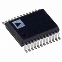
IC ADC 12BIT SRL 200KSPS 24-SSOP
Manufacturer
Analog Devices Inc
Datasheet
1.AD7853LARSZ-REEL.pdf
(34 pages)
Specifications of AD7853ARS
Rohs Status
RoHS non-compliant
Number Of Bits
12
Sampling Rate (per Second)
200k
Data Interface
8051, QSPI™, Serial, SPI™ µP
Number Of Converters
2
Power Dissipation (max)
33mW
Voltage Supply Source
Analog and Digital
Operating Temperature
-40°C ~ 85°C
Mounting Type
Surface Mount
Package / Case
24-SSOP (0.200", 5.30mm Width)


REV. B
CONFIGURING THE AD7853/AD7853L
AD7853/AD7853L as a Read-Only ADC
The AD7853/AD7853L contains fourteen on-chip registers
which can be accessed via the serial interface. In the majority of
applications it will not be necessary to access all of these regis-
ters. Figure 38 outlines a flowchart of the sequence which is
used to configure the AD7853/AD7853L as a Read-Only ADC.
APPLY SYNC (IF REQUIRED), SCLK AND READ
WAIT FOR AUTOMATIC CALIBRATION
Figure 40. Flowchart for Setting Up and Reading from the AD7853/AD7853L
POWER-ON, APPLY CLKIN SIGNAL,
CONVERSION RESULT ON DOUT PIN
DIN CONNECTED TO DGND
WAIT FOR BUSY SIGNAL
PULSE CONVST PIN
CONVERSION
INTERFACE
TO GO LOW
DURING
SERIAL
START
MODE
READ
DATA
?
?
NO
2, 3
YES
4, 5
AFTER CONVST RISING EDGE
WAIT APPROXIMATLY 200ns
–27–
In this case there is no writing to the on-chip registers and only
the conversion result data is read from the part. Interface Mode
1 cannot be used in this case as it is necessary to write to the
control register to set Interface Mode 1. Here the CLKIN signal
is applied directly after power-on, the CLKIN signal must be
present to allow the part to perform a calibration. This auto-
matic calibration will be completed approximately 32 ms after
the AD7853 has powered up (4 MHz CLK).
SCLK AUTOMATICALLY ACTIVE, READ
SYNC AUTOMATICALLY GOES LOW
CONVERSION RESULT ON DOUT PIN
AFTER CONVST RISING EDGE
PULSE CONVST PIN
AD7853/AD7853L
Related parts for AD7853ARS
Image
Part Number
Description
Manufacturer
Datasheet
Request
R

Part Number:
Description:
±1.7g Dual-Axis IMEMS Accelerometer Evaluation Board
Manufacturer:
Analog Devices Inc
Datasheet:

Part Number:
Description:
Inertial Sensor Evaluation System
Manufacturer:
Analog Devices Inc
Datasheet:
Part Number:
Description:
Manufacturer:
Analog Devices Inc
Datasheet:
Part Number:
Description:
Manufacturer:
Analog Devices Inc
Datasheet:
Part Number:
Description:
Manufacturer:
Analog Devices Inc
Datasheet:
Part Number:
Description:
Manufacturer:
Analog Devices Inc
Datasheet:
Part Number:
Description:
Manufacturer:
Analog Devices Inc
Datasheet:
Part Number:
Description:
Manufacturer:
Analog Devices Inc
Datasheet:
Part Number:
Description:
Manufacturer:
Analog Devices Inc
Datasheet:
Part Number:
Description:
Manufacturer:
Analog Devices Inc
Datasheet:
Part Number:
Description:
Manufacturer:
Analog Devices Inc
Datasheet:
Part Number:
Description:
Manufacturer:
Analog Devices Inc
Datasheet:
Part Number:
Description:
Manufacturer:
Analog Devices Inc
Datasheet: