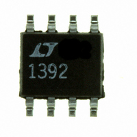
LTC1392CS8 Linear Technology, LTC1392CS8 Datasheet - Page 8

LTC1392CS8
Manufacturer Part Number
LTC1392CS8
Description
IC DATA ACQ SYSTEM 10BIT 8-SOIC
Manufacturer
Linear Technology
Type
Data Acquisition System (DAS)r
Datasheet
1.LTC1392CN8PBF.pdf
(12 pages)
Specifications of LTC1392CS8
Resolution (bits)
10 b
Sampling Rate (per Second)
25k
Data Interface
Serial
Voltage Supply Source
Single Supply
Voltage - Supply
4.5 V ~ 6 V
Operating Temperature
0°C ~ 70°C
Mounting Type
Surface Mount
Package / Case
8-SOIC (3.9mm Width)
Lead Free Status / RoHS Status
Contains lead / RoHS non-compliant
Available stocks
Company
Part Number
Manufacturer
Quantity
Price
Company:
Part Number:
LTC1392CS8
Manufacturer:
LNEAR
Quantity:
10 000
Company:
Part Number:
LTC1392CS8
Manufacturer:
LT
Quantity:
10 000
Part Number:
LTC1392CS8
Manufacturer:
LINEAR/凌特
Quantity:
20 000
Part Number:
LTC1392CS8#PBF
Manufacturer:
LINEAR/凌特
Quantity:
20 000
Company:
Part Number:
LTC1392CS8#TR
Manufacturer:
LINEAR
Quantity:
4 702
Company:
Part Number:
LTC1392CS8#TRPBF
Manufacturer:
LINEAR
Quantity:
6 567
APPLICATIONS
LTC1392
Measurement Mode Selections
The two bits of the input word following the Start Bit assign
the measurement mode for the requested conversion.
Table 1 shows the mode selections. Whenever there is a
mode change from another mode to temperature mea-
surement, a temperature mode initializing cycle is needed.
The first temperature data measurement after a mode
change should be ignored.
Table 1. Measurement Mode Selections
MSB-First/LSB-First (MSBF)
The output data of the LTC1392 is programmed for
MSB-first or LSB-first sequence using the MSBF bit. When
the MSBF bit is a logical one, data will appear on the D
line in MSB-first format. Logical zeros will be filled in
indefinitely following the last data bit to accommodate
longer word lengths required by some microprocessors.
When the MSBF bit is a logical zero, LSB-first data will
follow the normal MSB-first data on the D
CONVERSIONS
Temperature Conversion
The LTC1392 measures temperature through the use of an
on-chip, proprietary temperature measurement technique.
The temperature reading is provided in a 10-bit, unipolar
format. Table 2 describes the exact relationship of output
data to measured temperature or equation 1 can be used
to calculate the temperature.
Note that the LTC1392C is only specified for operation
over the 0 C to 70 C temperature range and the LTC1392I
over the – 40 C to 85 C range. Performance at tempera-
8
SELECT
Temperature ( C) = Output Code/4 – 130
1
0
0
1
1
SELECT
0
0
1
0
1
U
MEASUREMENT MODE
Temperature
Power Supply Voltage
Differential Input, 1V Full Scale
Differential Input, 0.5V Full Scale
INFORMATION
U
W
OUT
line.
U
OUT
(1)
tures outside these specified temperature ranges is not
guaranteed and errors may be greater than those shown in
the Electrical Characteristics table.
Table 2. Codes for Temperature Conversion
Voltage Supply (V
The LTC1392 measures supply voltage through the on-
chip V
10-bit, unipolar format. Table 3 describes the exact rela-
tionship of output data to measured V
can be used to calculate the measured V
The guaranteed supply voltage monitor range is from 4.5V
to 6V. Typical parts are able to maintain measurement
accuracy with V
DNL error plots shown on page 4 are measured with V
from 3.63V to 6.353V.
Table 3. Codes for Voltage Supply Conversion
Measured V
[(Output Code) • 4.84/1024] + 2.42
CC
OUTPUT CODE
OUTPUT CODE
1111111111
1111111110
1001101101
1001101100
1001101011
0000000001
0000000000
1011110110
1011110101
1000100010
0110111001
0110111000
supply line. The V
...
...
...
...
CC
CC
=
CC
as low as 3.25V. The typical INL and
) Monitor
CC
reading is provided in a
Supply Voltage (V
TEMPERATURE ( C)
CC
– 129.75
– 130.00
6.003V
5.998V
5.001V
4.504V
4.500V
125.75
125.50
CC
25.25
25.00
24.75
or equation (2)
...
...
...
...
.
CC
)
(2)
CC


