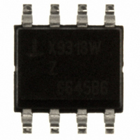
X9318WS8Z Intersil, X9318WS8Z Datasheet - Page 3

X9318WS8Z
Manufacturer Part Number
X9318WS8Z
Description
IC POT DGTL 10K OHM 8-SOIC
Manufacturer
Intersil
Series
XDCP™r
Datasheet
1.X9318WS8Z.pdf
(10 pages)
Specifications of X9318WS8Z
Taps
100
Resistance (ohms)
10K
Number Of Circuits
1
Temperature Coefficient
300 ppm/°C Typical
Memory Type
Non-Volatile
Interface
Up/Down (3-Wire)
Voltage - Supply
4.5 V ~ 5.5 V
Operating Temperature
0°C ~ 70°C
Mounting Type
Surface Mount
Package / Case
8-SOIC (3.9mm Width)
Resistance In Ohms
10K
Lead Free Status / RoHS Status
Lead free / RoHS Compliant
Available stocks
Company
Part Number
Manufacturer
Quantity
Price
Company:
Part Number:
X9318WS8Z
Manufacturer:
IDT
Quantity:
119
ABSOLUTE MAXIMUM RATINGS
Junction Temperature under bias...... -65°C to +135°C
Storage temperature ......................... -65°C to +150°C
Voltage on CS, INC, U/D and V
R
Lead temperature (soldering 10s) ..................... 300°C
I
POTENTIOMETER CHARACTERISTICS
(V
W
C
H
with respect to V
CC
H
Symbol
V
, R
(10s) ..............................................................±6mA
/C
RH
V
R
I
= 5V ± 10%, T
L
W
W
CC
)
W
/C
/
, R
RL
W
L
(5
to ground..........................................+10V
End to end resistance tolerance
R
Power rating
Wiper resistance
Wiper current
Noise
Resolution
Absolute linearity
Relative linearity
R
Ratiometric temperature coeffi-
cient
Potentiometer capacitances
Supply Voltage
H
TOTAL
/R
SS
(5),(6)
L
(7)
A
terminal voltage
................................. -1V to +7V
= Full Operating Temperature Range unless otherwise stated)
temperature coefficient
3
(5)
Parameter
(2)
(1)
CC
(5)
X9318
Min.
V
-3.0
-0.2
-20
-20
4.5
-1
SS
10/10/25
Typ.
COMMENT
Stresses above those listed under “Absolute Maximum
Ratings” may cause permanent damage to the device.
This is a stress rating only; functional operation of the
device (at these or any other conditions above those
listed in the operational sections of this specification) is
not implied. Exposure to absolute maximum rating con-
ditions for extended periods may affect device reliability.
±300
-120
40
1
(4)
Limits
Max.
+3.0
+0.2
+20
200
+20
5.5
+1
25
8
ppm/°C
ppm/°C
MI
MI
Unit
dBV
mW
mA
pF
%
%
Ω
V
V
(3)
(3)
See ordering information
for values
V
I
See test circuit
Ref: 1kHz
V(RH) = 8V,
V(RL) = 0V
See equivalent circuit
Test Conditions/Notes
W
SS
= 1mA
= 0V
September 14, 2005
FN8184.1


