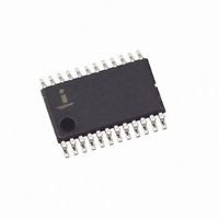
X9252WV24I-2.7 Intersil, X9252WV24I-2.7 Datasheet - Page 8

X9252WV24I-2.7
Manufacturer Part Number
X9252WV24I-2.7
Description
IC DCP QUAD 10K 256TAP 24-TSSOP
Manufacturer
Intersil
Series
XDCP™r
Datasheet
1.X9252YV24IZ-2.7.pdf
(20 pages)
Specifications of X9252WV24I-2.7
Taps
256
Resistance (ohms)
10K
Number Of Circuits
4
Temperature Coefficient
300 ppm/°C Typical
Memory Type
Non-Volatile
Interface
I²C, 2-Wire Serial
Voltage - Supply
2.7 V ~ 5.5 V
Operating Temperature
-40°C ~ 85°C
Mounting Type
Surface Mount
Package / Case
24-TSSOP
Resistance In Ohms
10K
Lead Free Status / RoHS Status
Contains lead / RoHS non-compliant
Test Circuit
Principles of Operation
The X9252 is an integrated circuit incorporating four resistor
arrays, their associated registers and counters, and the
serial interface logic providing direct communication
between the host and the digitally controlled potentiometers.
This section provides detail description of the following:
Resistor Array Description
The X9252 is comprised of four resistor arrays. Each array
contains 255 discrete resistive segments that are connected
in series. The physical ends of each array are equivalent to
the fixed terminals of a mechanical potentiometer (R
R
At both ends of each array and between each resistor
segment is a switch connected to the wiper (R
Li
- Resistor Array
- Up/Down Interface
- 2-wire Interface
inputs) (See Figure 1.)
A2, A1, A0
DS1, DS0
SDA
SCL
U/D
WP
CS
i = 0, 1, 2, and 3
Non-Volatile
DRi0, DRi1,
DRi2, and
Registers
DRi3
Four
Data
R
Volatile Status Register (SR)
W
(Shared by the Four DCPs)
8
Test Point
Interface Control and
Force
Current
FIGURE 1. DETAILED BLOCK DIAGRAM OF ONE DCP
Wi
Register
Counter
Volatile
Wiper
WCRi
8-bit
) pin.
Hi
and
X9252
Equivalent Circuit
Within each individual array only one switch may be turned
on at a time.
These switches are controlled by a Wiper Counter Register
(WCR). The 8-bits of the WCR (WCR[7:0]) are decoded to
select and enable one of 256 switches (see Table 1). Note
that each wiper has a dedicated WCR. When all bits of a
WCR are zeroes, the switch closest to the corresponding R
pin is selected. When all bits of a WCR are ones, the switch
closest to the corresponding R
The WCR is volatile and may be written directly. There are
four non-volatile Data Registers (DR) associated with each
WCR. Each DR can be loaded into WCR. All DRs and
WCRs can be read or written.
Power Up and Down Requirements
During power up, CS must be high, to avoid inadvertant
“store” operations. At power up, the contents of Data
Registers DR00, DR10, DR20, and DR30, are loaded into
the corresponding wiper counter register.
WCR[7:0]
WCR[7:0]
= 00 hex
= FF hex
Decoder
One
256
of
R
255
254
253
252
H
2
1
0
C
H
R
TOTAL
R
W
H
pin is selected.
C
W
C
L
R
November 14, 2005
L
R
R
R
Hi
Li
Wi
FN8167.2
L


