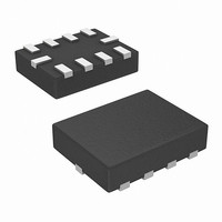
ISL23512WFRU10Z-TK Intersil, ISL23512WFRU10Z-TK Datasheet - Page 8

ISL23512WFRU10Z-TK
Manufacturer Part Number
ISL23512WFRU10Z-TK
Description
IC POT DGTL PB 16TP LN LP 10TQFN
Manufacturer
Intersil
Series
XDCP™r
Datasheet
1.ISL23512WFRU10Z-TK.pdf
(9 pages)
Specifications of ISL23512WFRU10Z-TK
Taps
16
Resistance (ohms)
10K
Number Of Circuits
1
Temperature Coefficient
80 ppm/°C Typical
Memory Type
Volatile
Interface
Pushbutton
Voltage - Supply
2.7 V ~ 5.5 V
Operating Temperature
-40°C ~ 125°C
Mounting Type
Surface Mount
Package / Case
10-UTQFN (10-µTQFN)
Resistance In Ohms
10K
Lead Free Status / RoHS Status
Lead free / RoHS Compliant
Power-up and Power-down Requirements
There are no restrictions on the power-up or power-down
conditions of V
potentiometer pins provided that V
than or equal to V
ramp rate specification is always in effect.
Pin Descriptions
R
The R
fixed terminals of a mechanical potentiometer. The minimum
voltage is V
R
relation to wiper movement direction.
R
The R
is equivalent to the movable terminal of a mechanical
potentiometer. The default wiper position at power-up is at
0 tap.
PU
The debounced PU input is used to increment the wiper
position. An on-chip pull-up holds the PU input HIGH. A
switch closure to ground or a LOW logic level will, after a
debounce time, move the wiper to the next adjacent higher
tap position.
PD
The debounced PD input is used to decrement the wiper
position. An on-chip pull-up holds the PD input HIGH. A
switch closure to ground or a LOW logic level will, after a
debounce time, move the wiper to the next adjacent lower
tap position.
Device Operation
There are three sections of the ISL23512: the input control,
the counter and decode section and the resistor array. The
input control section operates just like an up/down counter.
The output of this counter is decoded to turn on a single
electronic switch, connecting a point on the resistor array to
the wiper output. The resistor array is comprised of 15
individual resistors connected in series. At either end of the
array and between each resistor is an electronic switch that
transfers the potential at that point to the wiper.
The ISL23512 is designed to interface directly to two push
button switches for effectively moving the wiper up or down.
The PU and PD inputs increment or decrement a 4-bit counter
respectively. The output of this counter is decoded to select
one of the sixteen wiper positions along the resistive array.
The wiper increment input, PU and the wiper decrement input,
PD are both connected to an internal pull-up so that they
normally remain HIGH. When pulled LOW by an external
push button switch or a logic LOW level input, the wiper will be
switched to the next adjacent tap position.
H
W
H
and R
and R
W
H
and R
pin is the wiper terminal of the potentiometer, which
L
L
references the relative position of the terminal in
ss
L
and the maximum is V
cc
pins of the ISL23512 are equivalent to the
and the voltages applied to the
RH
and V
RL
, i.e., V
8
cc
cc
is always more positive
cc
. The terminology of
≥ V
RH,
V
RL
. The V
cc
ISL23512
Internal debounce circuitry prevents inadvertent switching of
the wiper position if PU or PD remain LOW for less than
15ms, typical. Each of the buttons can be pushed either
once for a single increment/decrement or continuously for
multiple increments/decrements. The number of
increments/decrements of the wiper position depend on how
long the button is being pushed. When making a continuous
push, after the first second, the increment/decrement speed
increases. For the first second, the device will be in the slow
scan mode. Then, if the button is held for longer than 1s, the
device will go into the fast scan mode. As soon as the button
is released, the ISL23512 will return to a stand-by condition.
If both PU and PD buttons are pulled low more than 15ms
from each other, all commands are ignored upon release of
ALL buttons.
The wiper, when at either fixed terminal, acts like its
mechanical equivalent and does not move beyond the last
position. That is, the counter does not wrap around when
clocked to either extreme.
Shutdown Mode
The ISL23512 enters into Shutdown Mode if both PU and
PD inputs are kept LOW for 2s. In this mode, the resistors
array is totally disconnected from its R
moved to the position closest to the R
Figure 13.
Note that PU and PD inputs must be pulled LOW within t
time window of 15ms (see “Shutdown Mode Timing” on
page 5) otherwise all commands will be ignored until both
inputs are released.
Holding either PU or PD input LOW for more than 15ms will
exit shutdown mode and return wiper to prior shutdown
position. If PU or PD will be held LOW for more than 250ms,
the ISL23512 will start auto-increment or auto-decrement of
wiper position.
R
The end-to-end resistance of the array will fluctuate once
V
CC
TOTAL
FIGURE 13. DCP CONNECTION IN SHUTDOWN MODE
is removed.
with V
CC
Removed
R
R
R
H
W
L
L
H
pin, as shown in
pin and the wiper is
January 21, 2008
FN6590.1
DB


