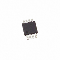
X93156WM8IZ Intersil, X93156WM8IZ Datasheet - Page 4

X93156WM8IZ
Manufacturer Part Number
X93156WM8IZ
Description
IC XDCP 32-TAP 12.5K 3WIRE 8MSOP
Manufacturer
Intersil
Series
XDCP™r
Datasheet
1.X93156UM8IZ-2.7T1.pdf
(7 pages)
Specifications of X93156WM8IZ
Taps
32
Resistance (ohms)
12.5K
Number Of Circuits
1
Temperature Coefficient
35 ppm/°C Typical
Memory Type
Non-Volatile
Interface
Up/Down (3-Wire)
Voltage - Supply
4.5 V ~ 5.5 V
Operating Temperature
-40°C ~ 85°C
Mounting Type
Surface Mount
Package / Case
8-MSOP, Micro8™, 8-uMAX, 8-uSOP,
Resistance In Ohms
12.5K
Lead Free Status / RoHS Status
Lead free / RoHS Compliant
Available stocks
Company
Part Number
Manufacturer
Quantity
Price
Company:
Part Number:
X93156WM8IZ-2.7
Manufacturer:
Intersil
Quantity:
30
Company:
Part Number:
X93156WM8IZ-2.7T1
Manufacturer:
Intersil
Quantity:
6 850
Endurance and Data Retention
Test Circuit #1
AC Electrical Specifications
DC Electrical Specifications
NOTES:
Minimum endurance
Data retention
(Notes 7, 8)
2. Absolute linearity is utilized to determine actual wiper voltage versus expected voltage = (V
3. Relative linearity is a measure of the error in step size between taps = V
4. 1 Ml = Minimum Increment = R
5. Typical values are for T
6. This parameter is periodically sampled and not 100% tested
7. This parameter is not 100% tested.
8. When performing multiple write operations, V
9. Parts are 100% tested at +25°C. Over-temperature limits established by characterization and are not production tested.
SYMBOL
SYMBOL
n = 1.. 29 only
t
t
t
CPH
CPH
CYC
V
C
V
t
t
t
t
t
t
I
I
I
DI
Cl
lD
lL
lH
lC
LI
LI
LI
PARAMETER
IH
IN
IL
CS to INC setup
INC HIGH to U/D change
U/D to INC setup
INC LOW period
INC HIGH period
INC Inactive to CS inactive
CS Deselect time (NO STORE)
CS Deselect time (STORE)
INC cycle time
CS input leakage current
CS input leakage current
INC, U/D input leakage current
CS, INC, U/D input HIGH voltage
CS, INC, U/D input LOW voltage
CS, INC, U/D input capacitance
TEST POINT
PARAMETER
A
= +25°C and nominal supply voltage.
200,000
MIN
100
4
TOT
V
PARAMETER
H
/31.
/R
Over recommended operating conditions unless otherwise specified.
Over recommended operating conditions unless otherwise specified. (Continued)
H
Data changes per bit
CC
V
V
V
V
Years
UNIT
CC
CC
IN
CC
must not decrease by more than 150mV from it’s initial value.
= V
= 3V, V
= 3V, CS = 0
= 5V, CS = 0
SS
to V
TEST CONDITIONS
IN
CC
= V
X93156
SS
, T
A
= +25°C, f = 1MHz
H(n+1)
Circuit #2 SPICE Macro Model
AC Conditions of Test
Input pulse levels
Input rise and fall times
Input reference levels
MIN
100
100
100
250
—[V
10
1
1
1
2
H(n)
R
H
+ Ml] = ±0.5 Ml, n = 1 .. 29 only.
10pF
H(n)
V
(Note 9)
CC
(actual)-V
MIN
-0.5
C
120
TYP
60
H
x 0.7
R
TOTAL
H(n)
(Note 5)
25pF
C
TYP
(expected)) = ±1 Ml Maximum.
W
100
200
0V to 3V
10ns
1.5V
MAX
10pF
C
L
V
V
(Note 9)
CC
CC
MAX
150
250
±1
10
+ 0.5
x 0.1
R
L
November 21, 2007
UNIT
ms
ns
ns
ns
µs
µs
µs
ns
µs
UNIT
µA
µA
µA
pF
FN8182.3
V
V


