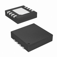
ISL95811UFRTZ Intersil, ISL95811UFRTZ Datasheet - Page 4

ISL95811UFRTZ
Manufacturer Part Number
ISL95811UFRTZ
Description
IC POT 256TAPS 5BYTES 8-TDFN
Manufacturer
Intersil
Series
XDCP™r
Datasheet
1.ISL95811WFUZ-T.pdf
(14 pages)
Specifications of ISL95811UFRTZ
Taps
256
Resistance (ohms)
50K
Number Of Circuits
1
Temperature Coefficient
4 ppm/°C Typical
Memory Type
Non-Volatile
Interface
I²C, 2-Wire Serial
Voltage - Supply
2.7 V ~ 5.5 V
Operating Temperature
-40°C ~ 125°C
Mounting Type
Surface Mount
Package / Case
8-TDFN
Resistance In Ohms
50K
Lead Free Status / RoHS Status
Lead free / RoHS Compliant
Analog Specifications
Operating Specifications
EEPROM SPECIFICATIONS
SERIAL INTERFACE SPECIFICATIONS
Hysteresis (Note 16) SDA and SCL Input Buffer Hysteresis
RESISTOR MODE (Measurements between RW and RL with RH not connected, or between RW and RH with RL not connected)
R
RDNL (Note 13) Differential Non-Linearity
RINL (Note 14)
offset
(Note 15, 16)
Cpin (Note 16)
SYMBOL
V
SYMBOL
TC
CC
I
LkgDig
(Note 12) Offset
t
Vpor
I
I
V
CC1
CC2
DCP
V
I
V
SB
t
R
Ramp
OL
D
IH
IL
Integral Non-Linearity
Resistance Temperature
Coefficient
V
(Volatile Write/Read)
V
(Non-volatile Write)
V
Leakage Current, at Pins SDA, SCL,
and WP Pins
DCP Wiper Response Time
Power-On Recall Voltage
V
Power-Up Delay
EEPROM Endurance
EEPROM Retention
WP, SDA, and SCL Input Buffer LOW
Voltage
WP, SDA, and SCL Input Buffer
HIGH Voltage
SDA Output Buffer LOW Voltage,
Sinking 4mA
WP, SDA, and SCL Pin Capacitance
CC
CC
CC
CC
Supply Current
Supply Current
Current (Standby)
Ramp Rate
PARAMETER
Over recommended operating conditions unless otherwise stated. (Continued)
PARAMETER
4
Over the recommended operating conditions unless otherwise specified.
DCP register set between 1 hex
and FF hex. Monotonic over all
tap positions.
DCP register set between 1 hex
and FF hex. Monotonic over all
tap positions
W option
U option
DCP register set between 20 hex and FF
hex
SCL falling edge of last bit of DCP Data
V
Temperature ≤ +55°C
f
Read and Volatile Write States only)
f
Non-volatile Write State only)
V
V
Voltage at pin from GND to V
Byte to wiper change
Minimum V
recall completed, and I
state
SCL
SCL
CC
CC
CC
= +5.5V, I
= +3.6V, I
above V
= 400kHz; SDA = Open; (for I
= 400kHz; SDA = Open; (for I
ISL95811
TEST CONDITIONS
CC
POR
TEST CONDITIONS
2
2
at which memory recall occurs
C Interface in Standby State
C Interface in Standby State
, to DCP Initial Value Register
2
C Interface in standby
CC
W option
U option
W option
U option
2
2
C, Active,
C, Active,
(Note 18)
-0.75
MIN
-0.5
-3
-1
0
0
1,000,000
(Note 18)
0.05*V
0.7*V
MIN
-0.3
1.8
0.2
50
-1
0
(Note 4)
CC
TYP
CC
±45
0.5
1
(Note 4)
TYP
(Note 18)
MAX
0.75
0.5
(Note 18) UNITS
3
1
5
2
0.3*V
V
MAX
100
2.6
CC
0.3
0.4
10
10
2
5
1
1
3
October 6, 2008
CC
+
(Note 11)
(Note 11)
(Note 11)
(Note 11)
(Note 11)
(Note 11)
ppm/°C
UNIT
FN6759.1
Cycles
MI
MI
MI
MI
MI
MI
Years
V/ms
mA
ms
µA
µA
µA
µA
pF
µs
V
V
V
V
V


