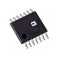
AD5280BRU200 Analog Devices Inc, AD5280BRU200 Datasheet - Page 15

AD5280BRU200
Manufacturer Part Number
AD5280BRU200
Description
IC DGTL POT 200K 256POS 14-TSSOP
Manufacturer
Analog Devices Inc
Datasheet
1.AD5280BRUZ50.pdf
(28 pages)
Specifications of AD5280BRU200
Rohs Status
RoHS non-compliant
Taps
256
Resistance (ohms)
200K
Number Of Circuits
1
Temperature Coefficient
30 ppm/°C Typical
Memory Type
Volatile
Interface
I²C, 2-Wire Serial
Voltage - Supply
4.5 V ~ 16.5 V, ±4.5 V ~ 5.5 V
Operating Temperature
-40°C ~ 85°C
Mounting Type
Surface Mount
Package / Case
14-TSSOP
Resistance In Ohms
200K
Number Of Elements
1
# Of Taps
256
Resistance (max)
200KOhm
Power Supply Requirement
Single/Dual
Interface Type
Serial (2-Wire/I2C)
Single Supply Voltage (typ)
15V
Dual Supply Voltage (typ)
±5V
Single Supply Voltage (min)
4.5V
Single Supply Voltage (max)
16.5V
Dual Supply Voltage (min)
±4.5V
Dual Supply Voltage (max)
±5.5V
Operating Temp Range
-40C to 85C
Operating Temperature Classification
Industrial
Mounting
Surface Mount
Pin Count
14
Lead Free Status / RoHS Status
Not Compliant
input voltage applied to Terminal A and Terminal B is
For a more accurate calculation that includes the effect of wiper
resistance, V
Table 6. Serial Format of Data Accepted from the I
S
where:
Abbreviation
S
P
A
X
AD1, AD0
R/W
A/B
RS
SD
O , O
D7, D6, D5, D4, D3, D2, D1, D0
2
START BY
MASTER
0
SDA
V
V
1
SCL
W
W
1
( )
( )
D
D
0
=
=
W
Slave Address Byte
can be found as
256
R
D
1 1
WB
0
R
1
AB
V
( )
D
A
START BY
1
MASTER
+
SLAVE ADDRESS BYTE
AD1
V
SDA
SCL
256 −
A
0
256
+
FRAME 1
R
1
WA
AD
0
D
R
AB
V
( )
D
B
1 AD1
1
Figure 46. Reading Data from a Previously Selected RDAC Register in Write Mode
0
Midscale reset, active high (only affects selected channel)
Equals
Start condition
Stop condition
Acknowledge
Don’t care
Package pin programmable address bits
Read enable at high and write enable at low
RDAC subaddress select; 0 = RDAC1 and 1 = RDAC2
Shutdown; same as SHDN pin operation except inverse logic (only affects selected channel)
Output logic pin latched values; default Logic 0
Data bits
V
R/
W
B
1
AD0
SLAVE ADDRESS BYTE
0
A
R/W
AD5280/5282
FRAME 1
ACK. BY
A /B
1
9
1
Figure 45. Writing to the RDAC Register
A/B
2
RS
C Bus
AD1 AD0 R/W
1
Instruction Byte
RS
S
D
Rev. C | Page 15 of 28
(3)
(4)
INSTRUCTION BYTE
SD
AD5280/AD5282
O
FRAME 2
ACK. BY
1
O1
9
O
O2
DATA BYTE FROM PREVIOUSLY SELECTED
2
D7
Operation of the digital potentiometer in divider mode results
in a more accurate operation over temperature. Unlike rheostat
mode, the output voltage is dependent mainly on the ratio of
the internal resistors R
values; therefore, the temperature drift reduces to 5 ppm/°C.
1
X
X X X
D6
X
D5
AD5280/AD5282
X
FRAME 2
ACK. BY
D4
A
9
D3
D7
D7
1
D2
D6
D6
WA
D1
and R
D5
D0
NO ACK. BY
DATA BYTE
D
5
FRAME 3
MASTER
D4
9
WB
A
9
Data Byte
STOP BY
MASTER
D
4
D3
and not on the absolute
D2
AD5280/AD5282
D
3
D1
D
2
AD5280/5282
D0
ACK. BY
D
1
STOP BY
MASTER
D
0
A
P


