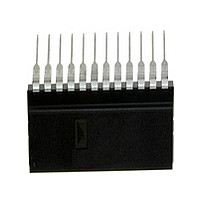
AD7868BN Analog Devices Inc, AD7868BN Datasheet - Page 10

AD7868BN
Manufacturer Part Number
AD7868BN
Description
Manufacturer
Analog Devices Inc
Datasheet
1.AD7868BN.pdf
(16 pages)
Specifications of AD7868BN
Converter Type
ADC/DAC
Resolution
12b
Number Of Dac's
Single
Data Rate
0.083MSPS
Digital Interface Type
Serial (2-Wire)
Pin Count
24
Package Type
PDIP
Lead Free Status / Rohs Status
Compliant
AD7868
Figure 11. AD7868 DAC Dynamic Performance Test Circuit
The digitizer sampling is synchronized with the DAC update
rate to ease FFT calculations. The digitizer samples the DAC
output after the output has settled to its new value. Therefore, if
the digitizer were to sample the output directly it would effec-
tively be sampling a dc value each time. As a result, the dynamic
performance of the DAC would not be measured correctly. Us-
ing the digitizer directly on the DAC output would give better
results than the actual performance of the DAC. Using a filter
between the DAC and the digitizer means that the digitizer
samples a continuously moving signal and the true dynamic per-
formance of the AD7868 DAC output is measured.
Figure 12 shows a typical 2048 point Fast Fourier Transform
plot for the AD7868 DAC with an update rate of 83 kHz and an
output frequency of 1 kHz. The SNR obtained from the graph is
73 dBs.
Some applications will require improved performance versus fre-
quency from the AD7868 DAC. In these applications, a simple
sample-and-hold circuit such as that outlined in Figure 13 will
extend the very good performance of the DAC to 20 kHz. Other
applications will already have an inherent sample-and-hold
function following the AD7868 DAC output. An example of
this type of application is driving a switched-capacitor filter
where the updating of the DAC is synchronized with the
switched-capacitor filter. This inherent sample-and-hold
function also extends the frequency range performance.
Performance versus Frequency
The typical performance plots of Figures 14 and 15 show the
AD7868’s DAC performance over a wide range of input fre-
CONTROLLER
MICRO-
Figure 12. AD7868 DAC FFT Plot
AD7868
DAC
LOW-PASS
FILTER
DIGITIZER
16-BIT
–10–
quencies at an update rate of 83 kHz. The plot of Figure 14 is
without a sample-and-hold on the DAC output while the plot of
Figure 15 is generated with a sample-and-hold on the output.
LDAC
Figure 15. DAC Performance vs. Frequency (Sample-and-
Hold)
Figure 14. DAC Performance vs. Frequency (No Sample-
and-Hold)
80
70
60
50
40
30
20
10
80
70
60
50
40
30
20
10
Figure 13. DAC Sample-and-Hold Circuit
0
AD7868*
LDAC
0
0
0
1
V
5
OUT
DELAY
SHOT
ONE
1µs
FREQUENCY – kHz
FREQUENCY – kHz
Q
2k2
R1
2
*ADDITIONAL PINS OMITTED FOR CLARITY
10
S1
ADG201HS
T
A
3
= +25 C
IN1
T
A
D1
= +25 C
2k2
R2
15
330pF
C9
AD711
4
REV. B
20
5


