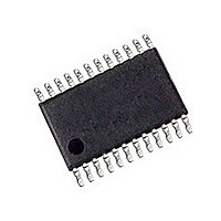
CAT5251YI-50-TE13 ON Semiconductor, CAT5251YI-50-TE13 Datasheet - Page 4

CAT5251YI-50-TE13
Manufacturer Part Number
CAT5251YI-50-TE13
Description
Manufacturer
ON Semiconductor
Datasheet
1.CAT5251YI-50-TE13.pdf
(15 pages)
Specifications of CAT5251YI-50-TE13
Number Of Elements
4
# Of Taps
256
Resistance (max)
50KOhm
Power Supply Requirement
Single
Interface Type
Serial (SPI)
Single Supply Voltage (typ)
3.3/5V
Dual Supply Voltage (typ)
Not RequiredV
Single Supply Voltage (min)
2.5V
Single Supply Voltage (max)
6V
Dual Supply Voltage (min)
Not RequiredV
Dual Supply Voltage (max)
Not RequiredV
Operating Temp Range
-40C to 85C
Operating Temperature Classification
Industrial
Mounting
Surface Mount
Pin Count
24
Lead Free Status / Rohs Status
Compliant
Stresses exceeding Maximum Ratings may damage the device. Maximum Ratings are stress ratings only. Functional operation above the
Recommended Operating Conditions is not implied. Extended exposure to stresses above the Recommended Operating Conditions may affect
device reliability.
1. The minimum DC input voltage is –0.5 V. During transitions, inputs may undershoot to –2.0 V for periods of less than 20 ns. Maximum DC
2. Latch−up protection is provided for stresses up to 100 mA on address and data pins from –1 V to V
Table 2. ABSOLUTE MAXIMUM RATINGS
Table 1. PIN DESCRIPTION
Pin #
Temperature Under Bias
Storage Temperature
Voltage on any Pin with Respect to V
V
Package Power Dissipation Capability (T
Lead Soldering Temperature (10 s)
Wiper Current
10
12
13
14
15
16
17
18
19
20
21
22
23
24
voltage on output pins is V
11
CC
1
2
3
4
5
6
7
8
9
with Respect to Ground
Name
HOLD
GND
SCK
R
V
R
R
R
R
R
R
R
R
R
WP
R
R
SO
NC
CS
NC
A0
A1
SI
W3
CC
W0
W1
W2
H3
H0
H1
H2
L3
L0
L1
L2
Serial Data Output
Device Address, LSB
Wiper Terminal for Potentiometer 3
High Reference Terminal for
Potentiometer 3
Low Reference Terminal for
Potentiometer 3
No Connect
Supply Voltage
Low Reference Terminal for
Potentiometer 0
High Reference Terminal for
Potentiometer 0
Wiper Terminal for Potentiometer 0
Chip Select
Write Protection
Serial Input
Device Address
Low Reference Terminal for
Potentiometer 1
High Reference Terminal for
Potentiometer 1
Wiper Terminal for Potentiometer 1
Ground
No Connect
Wiper Terminal for Potentiometer 2
High Reference Terminal for
Potentiometer 2
Low Reference Terminal for
Potentiometer 2
Bus Serial Clock
Hold
CC
+ 0.5 V, which may overshoot to V
Function
SS
Parameter
(Notes 1, 2)
A
= 25°C)
http://onsemi.com
CC
4
+ 2.0 V for periods of less than 20 ns.
Serial Bus Protocol
protocol. The synchronous Serial Peripheral Interface (SPI)
helps the CAT5251 to interface directly with many of
today’s popular microcontrollers. The CAT5251 contains an
8−bit instruction register. The instruction set and the
operation codes are detailed in Table 13, Instruction Set on
page 9.
byte will be received. The part is accessed via the SI pin, with
data being clocked in on the rising edge of SCK. The first
byte contains one of the six op−codes that define the
operation to be performed.
Device Operation
SPI serial interface logic, four 8−bit wiper control registers
and sixteen 8−bit, non−volatile memory data registers. Each
resistor array contains 255 separate resistive elements
connected in series. The physical ends of each array are
equivalent to the fixed terminals of a mechanical
potentiometer (R
may be interchanged. The tap positions between and at the
ends of the series resistors are connected to the output wiper
terminals (R
point for each potentiometer is connected to its wiper
terminal at a time and is determined by the value of the wiper
control register. Data can be read or written to the wiper
control registers or the non−volatile memory data registers
via the SPI bus. Additional instructions allow data to be
transferred between the wiper control registers and each
respective potentiometer’s non−volatile data registers. Also,
the device can be instructed to operate in an “increment/
decrement” mode.
The CAT5251 supports the SPI bus data transmission
After the device is selected with CS going low the first
The CAT5251 is four resistor arrays integrated with an
W
) by a CMOS transistor switch. Only one tap
H
and R
−2.0 to +V
L
−55 to +125
−65 to +150
−2.0 to +7.0
). R
CC
Ratings
300
1.0
+ 1 V.
±6
H
and R
CC
+2.0
L
are symmetrical and
Units
mA
°C
°C
°C
W
V
V


