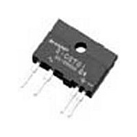
S202S12 Sharp Electronics, S202S12 Datasheet - Page 8

S202S12
Manufacturer Part Number
S202S12
Description
Manufacturer
Sharp Electronics
Datasheet
1.S202S12.pdf
(13 pages)
Specifications of S202S12
Input Type
DC
Output Type
AC
Input Voltage (max)
1.4V
Output Voltage (max)
600V
Input Current (max)
50mA
Output Current
8A
Isolation Voltage
4kV
Package Type
SIP
Output Device
Triac
Pin Count
4
Mounting
Through Hole
Operating Temp Range
-20C to 80C
Operating Temperature Classification
Commercial
Rad Hardened
No
Lead Free Status / Rohs Status
Not Compliant
Available stocks
Company
Part Number
Manufacturer
Quantity
Price
Company:
Part Number:
S202S12
Manufacturer:
MOLEX
Quantity:
10 000
Part Number:
S202S12
Manufacturer:
SHARP
Quantity:
20 000
■ Design Considerations
(
Output
∗
Operating temperature
) See Fig.2 about derating curve (I
Input
● Recommended Operating Conditions
● Design guide
In order for the SSR to turn off, the triggering current (l
For over voltage protection, a Varistor may be used.
A varistor used for the above mentioned scenarios should be located as close to the main output triac as
possible.
Particular attention needs to be paid when utilizing SSRs that incorporate zero crossing circuitry.
If the phase difference between the voltage and the current at the output pins is large enough, zero crossing
type SSRs cannot be used. The result, if zero crossing SSRs are used under this condition, is that the SSR
may not turn on and off irregardless of the input current. In this case, only a non zero cross type SSR should
be used in combination with the above mentioned snubber circuit selection process.
The load current should be within the bounds of derating curve. (Refer to Fig.2)
Also, please use the optional heat sink when necessary.
In case the optional heat sink is used and the isolation voltage between the device and the optional heat sink
is needed, please locate the insulation sheet between the device and the heat sink.
When the optional heat sink is equipped, please set up the M3 screw-fastening torque at 0.3 to 0.5N・m.
In order to dissipate the heat generated from the inside of device effectively, please follow the below sugges-
tions.
(a) Make sure there are no warps or bumps on the heat sink, insulation sheet and device surface.
(b) Make sure there are no metal dusts or burrs attached onto the heat sink, insulation sheet and device sur-
(c) Make sure silicone grease is evenly spread out on the heat sink, insulation sheet and device surface.
Silicone grease to be used is as follows;
1) There is no aged deterioration within the operating temperature ranges.
2) Base oil of grease is hardly separated and is hardly permeated in the device.
3) Even if base oil is separated and permeated in the device, it should not degrade the function of a device.
Recommended grease : G-746 (Shin-Etsu Chemical Co., Ltd.)
Input signal current at ON state
Input signal current at OFF state
Load supply voltage
Load supply current
Frequency
face.
Parameter
T
(rms) vs. ambient temperature).
S102S12
S202S12
: G-747 (Shin-Etsu Chemical Co., Ltd.)
: SC102 (Dow Corning Toray Silicone Co., Ltd.)
V
I
I
OUT
Symbol
I
OUT
F
F
(OFF)
(ON)
T
(rms)
f
opr
(rms)
8
Conditions
F
) must be 0.1mA or less.
−
−
−
−
−
−
MIN.
−20
0.1
16
80
80
47
0
I
T
S102S12 Series
S202S12 Series
(rms)×80%(
Sheet No.: D4-A02901EN
MAX.
120
240
0.1
24
63
80
∗
)
Unit
mA
mA
mA
Hz
˚C
V


