S202T01 Sharp Electronics, S202T01 Datasheet
S202T01
Specifications of S202T01
Available stocks


Related parts for S202T01


S202T01 Summary of contents
Page 1
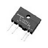
... Zero cross type is also available. (S102T02 Series/ S202T02 Series) ■ Description S102T01 Series and S202T01 Series Solid State Relays (SSR) are an integration of an infrared emitting diode (IRED), a Phototriac Detector and a main output Triac. These devices are ideally suited for controlling high voltage AC loads with solid state reliability while providing 3 ...
Page 2
... Product mass : approx. 3.5g 2 S102T01 Series S202T01 Series (Unit : mm) ±0.2 ±0.2 3 Common to pin No.2 ±0.2 UL mark CSA mark Epoxy resin Date code (2 digit) + − ±0.2 3-1.2 ±0.2 3-1.4 ±0.1 0.4 ± ...
Page 3
... Rank mark There is no rank mark indicator and currently there are no rank offered for this device. 2nd digit Month of production Month Mark January 1 February 2 March 3 April 4 May 5 June 6 July 7 August 8 September 9 October O November N December D 3 S102T01 Series S202T01 Series Sheet No.: D4-A01501EN ...
Page 4
... Resistance load T V (rms)=100V, AC50Hz (rms)=2A, Resistance load T t off V (rms)=200V, AC50Hz (rms)=2A, Resistance load T 4 S102T01 Series S202T01 Series Soldering area (T =25˚C) a MIN. TYP. MAX. Unit − 1.2 1.4 − − 100 − − 100 =20mA − ...
Page 5
... S102T01 Model No. S202T01 Please contact a local SHARP sales representative to see the actual status of the production. I [mA DRM (V =12V, D [V] R =30Ω) L MAX.8 400 MAX.8 600 I [mA DRM (V =12V, D [V] R =30Ω) L MAX.8 400 MAX.8 600 5 S102T01 Series S202T01 Series Sheet No.: D4-A01501EN ...
Page 6
... Fig.4 Surge Current vs. Power-on Cycle 1.6 1.8 (mA) Fig.6 Maximum ON-state Power Dissipation vs. RMS ON-state Current 2.5 V =12V D 1.5 0.5 75 100 (˚ S102T01 Series S202T01 Series 0 − 100 Ambient temperature T (˚ f=60Hz T =25˚C start Power-on cycle (Times) T =25˚ ...
Page 7
... Ambient temperature T Remarks : Please be aware that all data in the graph are just for reference. Fig.7-b Repetitive Peak OFF-state Current vs. Ambient Temperature (S202T01) − =400V D −4 10 −5 10 −6 10 −7 10 −8 10 − 100 −25 (˚C) ...
Page 8
... Locate snubber circuit between output terminals I (rms) OUT (Cs=0.022µF, Rs=47Ω) f − T − opr ) must be 0.1mA or less increases faster than rated dV/dt, the Triac may turn on. To avoid this situation, 8 S102T01 Series S202T01 Series MIN. MAX. Unit 0 120 V 80 240 ...
Page 9
... Standard Circuit Tr1 ✩ For additional design assistance, please review our corresponding Optoelectronic Application Notes. 3.8mm MIN. S102T01 S202T01 3 2 Load SSR Line Surge absorption circuit (Snubber circuit S102T01 Series S202T01 Series Sheet No.: D4-A01501EN ...
Page 10
... Please solder within one time. Other notices Please test the soldering method in actual condition and make sure the soldering works fine, since the impact on the junction between the device and PCB varies depending on the tooling and soldering conditions. 10 S102T01 Series S202T01 Series Sheet No.: D4-A01501EN ...
Page 11
... This product shall not contain the following materials. And they are not used in the production process for this device. Regulation substances : CFCs, Halon, Carbon tetrachloride, 1.1.1-Trichloroethane (Methylchloroform) Specific brominated flame retardants such as the PBBOs and PBBs are not used in this product at all. 11 S102T01 Series S202T01 Series Sheet No.: D4-A01501EN ...
Page 12
... Sleeve package Package materials Sleeve : HIPS Stopper : Olefine-Elastomer Package method MAX. 25pcs of products shall be packaged in a sleeve. Both ends shall be closed by stoppers. MAX. 20 sleeves in one case. Sleeve outline dimensions 1.1 1.1 4.7 7.6 (8.5) 12 S102T01 Series S202T01 Series (Unit : mm) Sheet No.: D4-A01501EN ...
Page 13
... SHARP. Express written permission is also required before any use of this publication may be made by a third party. · Contact and consult with a SHARP representative if there are any questions about the contents of this pub- lication. 13 S102T01 Series S202T01 Series Sheet No.: D4-A01501EN ...