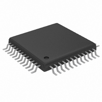
MAX5856AECM+TD Maxim Integrated Products, MAX5856AECM+TD Datasheet - Page 14

MAX5856AECM+TD
Manufacturer Part Number
MAX5856AECM+TD
Description
IC DAC 8BIT DUAL 300MSPS 48-TQFP
Manufacturer
Maxim Integrated Products
Datasheet
1.MAX5856AECMD.pdf
(23 pages)
Specifications of MAX5856AECM+TD
Settling Time
11ns
Number Of Bits
8
Data Interface
Parallel
Number Of Converters
2
Voltage Supply Source
Single Supply
Power Dissipation (max)
792mW
Operating Temperature
-40°C ~ 85°C
Mounting Type
Surface Mount
Package / Case
48-TQFP Exposed Pad, 48-eTQFP, 48-HTQFP, 48-VQFP
Lead Free Status / RoHS Status
Lead free / RoHS Compliant
Dual 8-Bit, 300Msps DAC with 4x/2x/1x
Interpolation Filters and PLL
At power-up, the MAX5856A is configured in no-inter-
polation mode with a gain adjustment setting of 0dB
and a fully operational converter. In shutdown, the
MAX5856A consumes only 1µA of supply current, and
in standby the current consumption is 4.4mA. Wake-up
time from standby mode to normal operation is 0.7µs.
The MAX5856A features a 2-stage, 2x digital interpolating
filter based on 43-tap and 23-tap FIR topology. F1EN and
F2EN enable the interpolation filters. F1EN = 1 enables
the first filter for 2x interpolation and F2EN = 1 enables
the second filter for combined 4x interpolation. To bypass
and disable both interpolation filters (no-interpolation
mode or 1x mode) set F1EN = F2EN = 0. When set for 1x
mode the filters are powered down and consume virtually
no current. An illegal condition is defined by: F1EN = 0,
F2EN = 1 (see Table 2 for configuration modes).
Table 1. Control Word Format and Function
Table 2. Configuration Modes
X = Don’t care.
F1EN = 0, F2EN = 1: illegal condition.
14
CONTROL WORD
No interpolation
2x interpolation
4x interpolation
MSB
Power-down
Power-up
Standby
MODE
______________________________________________________________________________________
DACEN
PD
F2EN
F1EN
PD
G3
G2
G1
G0
DACEN
Power-down; The part enters power-down mode if PD = 1.
DAC Enable; When DACEN = 0 and PD = 0, the part enters standby mode.
Filter Enable; When F2EN = 1 and F1EN = 1, 4x interpolation is enabled. When F2EN = 0, the interpolation
mode is determined by F1EN.
Filter Enable; When F1EN = 1 and F2EN = 0, 2x interpolation is active. With F1EN = 0 and F2EN = 0, the
interpolation is disabled.
Bit 3 (MSB) of gain adjust word.
Bit 2 of gain adjust word.
Bit 1 of gain adjust word.
Bit 0 (LSB) of gain adjust word.
PD
0
0
0
0
1
0
Device Power-Up and
DACEN
Interpolation Filters
States of Operation
X
1
1
1
0
1
F2EN
F2EN
X
X
X
0
0
1
F1EN
F1EN
0
1
1
X
X
X
The programmable interpolation filters multiply the
1) Image separation reduces complexity of analog
2) Lower input data rates eliminate board-level high-
3) Sin(x)/x rolloff is reduced over the effective bandwidth.
Figure 2 shows an application circuit and Figure 3 illus-
trates a practical example of the benefits when using
the MAX5856A with 4x-interpolation mode. The exam-
ple illustrates signal synthesis of a 20MHz IF with a
±10MHz bandwidth. Three options can be considered
to address the design requirements. The tradeoffs for
each solution are shown in Table 4.
MAX5856A input data rate by a factor of two or four to
separate the reconstructed waveform spectrum and the
first image. The original spectral images, appearing
around multiples of the DAC input data rate, are attenu-
ated at least 60dB by the internal digital filters. This fea-
ture provides three benefits:
Table 3. Gain Difference Setting
FUNCTION
GAIN ADJUSTMENT ON
reconstruction filters.
speed data transmission.
G3
CHANNEL A (dB)
-0.35
+0.4
0
G2
G3
0
1
1
G1
G2
0
0
1
G1
0
0
1
G0
LSB
G0
0
0
1


