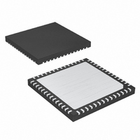
MAX5732AUTN+ Maxim Integrated Products, MAX5732AUTN+ Datasheet - Page 23

MAX5732AUTN+
Manufacturer Part Number
MAX5732AUTN+
Description
IC DAC 16BIT 32CHAN SER 56-TQFN
Manufacturer
Maxim Integrated Products
Datasheet
1.MAX5732BUTNT.pdf
(28 pages)
Specifications of MAX5732AUTN+
Settling Time
20µs
Number Of Bits
16
Data Interface
MICROWIRE™, QSPI™, Serial, SPI™
Number Of Converters
32
Voltage Supply Source
Analog and Digital
Power Dissipation (max)
2.5W
Operating Temperature
0°C ~ 85°C
Mounting Type
Surface Mount
Package / Case
56-TQFN
Lead Free Status / RoHS Status
Lead free / RoHS Compliant
Figure 7. Stand-Alone Configuration
Figure 8. Example of a Parallel Configuration with Read-Back
Figure 9. Read Data Timing When Not Daisy Chained
CS (DSP)
DOUT(0)
CS (µC)
DIN(0)
SCLK
OR
CONTROLLER
C2
DEVICE
CONTROLLER
DEVICE
C1
C0 A5 A4 A3 A2 A1 A0 Sp Sp Sp Sp Sp Sp Sp D15 D14 D13 D12 D11 D10 D9 D8 D7 D6 D5 D4 D3 D2 D1 D0
______________________________________________________________________________________
1 OR 0
1 OR 0
1 OR 0
1 OR 0
32-Channel, 16-Bit, Voltage-Output
DIN
SCLK
CS
DSP
DIN
SCLK
CS
DSP
DIN
SCLK
CS
DSP
DIN
SCLK
CS
DSP
MAX573_
MAX573_
MAX573_
MAX573_
DOUT
DOUT
DOUT
DOUT
DACs with Serial Interface
The MAX5732–MAX5735 support daisy-chain connec-
tions of multiple devices. The default (power-up) config-
uration for the MAX5732–MAX5735 assumes that the
device may be part of a daisy chain of devices. DOUT
follows DIN after 32 clock cycles. For a read command,
DOUT provides read data (instead of the data value
shifted in) in the next cycle following a CS rising edge.
Figures 5 and 6 show examples of daisy-chain
data sequences.
The MAX5732–MAX5735 feature a software-controlled
low-power shutdown mode. When bit 11 of the configu-
ration register is a logic high, the analog section of the
device is disabled, and the outputs go high impedance.
In shutdown, supply current is reduced to 50µA. Data
stored in the DAC and input registers is retained, and
the device outputs return to their previous values when
the device is brought out of shutdown. The serial inter-
face remains active while the device is in shutdown.
The MAX5732–MAX5735 monitor the four power supplies
and maintain the output buffers in a known state until suffi-
cient voltage is available to ensure that no output glitches
occur. Once the minimum voltage threshold has been
passed, the device outputs come up in the clear state (all
outputs = 0). For proper power sequencing, V
applied first. Power sequencing is not necessary if V
connected to AGND.
D15 D14 D13 D12 D11 D10 D9 D8 D7 D6 D5 D4 D3 D2 D1 D0
Shutdown Mode
Power-Up State
Read-Data Format
SS
must be
SS
23
is


