ADSP-2185NKCA-320 Analog Devices Inc, ADSP-2185NKCA-320 Datasheet - Page 24
ADSP-2185NKCA-320
Manufacturer Part Number
ADSP-2185NKCA-320
Description
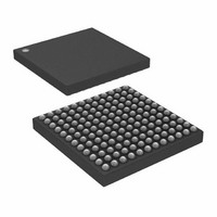
IC DSP 16BIT 80MHZ 144CSPBGA
Manufacturer
Analog Devices Inc
Series
ADSP-21xxr
Type
Fixed Pointr
Datasheet
1.ADSP-2185NKSTZ-320.pdf
(48 pages)
Specifications of ADSP-2185NKCA-320
Rohs Status
RoHS non-compliant
Interface
Host Interface, Serial Port
Clock Rate
80MHz
Non-volatile Memory
External
On-chip Ram
80kB
Voltage - I/o
1.8V, 2.5V, 3.3V
Voltage - Core
1.80V
Operating Temperature
0°C ~ 70°C
Mounting Type
Surface Mount
Package / Case
144-CSPBGA
Device Core Size
16b
Architecture
Enhanced Harvard
Format
Fixed Point
Clock Freq (max)
80MHz
Mips
80
Device Input Clock Speed
80MHz
Ram Size
80KB
Program Memory Size
Not RequiredKB
Operating Supply Voltage (typ)
1.8/2.5/3.3V
Operating Supply Voltage (min)
1.71V
Operating Supply Voltage (max)
1.89/3.6V
Operating Temp Range
0C to 70C
Operating Temperature Classification
Commercial
Mounting
Surface Mount
Pin Count
144
Package Type
CSPBGA
Lead Free Status / Rohs Status
Not Compliant
Available stocks
Company
Part Number
Manufacturer
Quantity
Price
Company:

Part Number:
ADSP-2185NKCA-320
Manufacturer:
Analog Devices Inc
Quantity:
10 000


ADSP-218xN
ESD DIODE PROTECTION
During the power-up sequence of the DSP, differences in the
ramp-up rates and activation time between the two supplies can
cause current to flow in the I/O ESD protection circuitry. To
prevent damage to the ESD diode protection circuitry, Analog
Devices recommends including a bootstrap Schottky diode.
The bootstrap Schottky diode is connected between the core
and I/O power supplies, as shown in
ADSP-218xN processor from partially powering the I/O supply.
Including a Schottky diode will shorten the delay between the
supply ramps and thus prevent damage to the ESD diode pro-
tection circuitry. With this technique, if the core rail rises ahead
of the I/O rail, the Schottky diode pulls the I/O rail along with
the core rail.
Table 13. Example Power Dissipation Calculation
1
Parameters
Address
Data Output, WR
RD
CLKOUT, DMS
Total power dissipation for this example is P
DC INPUT
SOURCE
Figure 17. Dual Voltage Schottky Diode
REGULATOR
REGULATOR
I/O VOLTAGE
VOLTAGE
CORE
No. of Pins
7
9
1
2
INT
Figure
+ 45.72 mW.
V
V
DDEXT
DDINT
17. It protects the
ADSP-218xN
Rev. A | Page 24 of 48 | August 2006
1
× C (pF)
10
10
10
10
× V
3.3
3.3
3.3
3.3
POWER DISSIPATION
To determine total power dissipation in a specific application,
the following equation should be applied for each output: C
V
where:
C = load capacitance.
f = output switching frequency.
Example: In an application where external data memory is used
and no other outputs are active, power dissipation is calculated
as follows:
Assumptions:
Total Power Dissipation = P
P
(C
ple in
2
2
2
2
DDEXT
DD
INT
• External data memory is accessed every cycle with 50% of
• External data memory writes occur every other cycle with
• Each address and data pin has a 10 pF total load at the pin.
• Application operates at V
2
the address pins switching.
50% of the data pins switching.
= internal power dissipation from
V
2
Table
DDEXT
(V)
f
2
13.
f) is calculated for each output, as in the exam-
× f (MHz)
20.0
20.0
20.0
40.0
INT
DDEXT
+ (C
= 3.3 V and t
V
Figure 22 on Page
DDEXT
2
PD (mW)
15.25
19.59
45.72
2.18
8.70
f)
CK
= 30 ns.
27.
Related parts for ADSP-2185NKCA-320
Image
Part Number
Description
Manufacturer
Datasheet
Request
R

Part Number:
Description:
±1.7g Dual-Axis IMEMS Accelerometer Evaluation Board
Manufacturer:
Analog Devices Inc
Datasheet:

Part Number:
Description:
Inertial Sensor Evaluation System
Manufacturer:
Analog Devices Inc
Datasheet:
Part Number:
Description:
Manufacturer:
Analog Devices Inc
Datasheet:
Part Number:
Description:
Manufacturer:
Analog Devices Inc
Datasheet:
Part Number:
Description:
Manufacturer:
Analog Devices Inc
Datasheet:
Part Number:
Description:
Manufacturer:
Analog Devices Inc
Datasheet:
Part Number:
Description:
Manufacturer:
Analog Devices Inc
Datasheet:
Part Number:
Description:
Manufacturer:
Analog Devices Inc
Datasheet:
Part Number:
Description:
Manufacturer:
Analog Devices Inc
Datasheet:
Part Number:
Description:
Manufacturer:
Analog Devices Inc
Datasheet:
Part Number:
Description:
Manufacturer:
Analog Devices Inc
Datasheet:
Part Number:
Description:
Manufacturer:
Analog Devices Inc
Datasheet:
Part Number:
Description:
Manufacturer:
Analog Devices Inc
Datasheet: