20-101-1306 Rabbit Semiconductor, 20-101-1306 Datasheet - Page 23
20-101-1306
Manufacturer Part Number
20-101-1306
Description
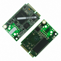
CORE MODULE RCM5750
Manufacturer
Rabbit Semiconductor
Type
Serial to Ethernetr
Datasheet
1.20-101-1306.pdf
(119 pages)
Specifications of 20-101-1306
Module/board Type
MPU Core Module
Number Of I/os
32
Ethernet Connection Type
10/100 Base-T
Memory Type
Flash
Operating Voltage
3.3 V
Operating Current
70 mA
Operating Temperature Range
- 40 C to + 85 C
Board Size
30 mm x 51 mm x 3 mm
Product
Modules
For Use With/related Products
RCM5750
Lead Free Status / RoHS Status
Lead free / RoHS Compliant
Other names
316-1183


The Serial Communication accessory board needs to be installed to run the following serial sam-
ple program in the
ing on your MiniCore model. This accessory board is included only with the Deluxe Development
Kit.
To install the Serial Communication accessory board, insert the strip of header pins included with
the accessory board into the socket at J12 on the bottom side of the Serial Communication acces-
sory board. Then line up the Serial Communication accessory board with the Interface Board or
Digital I/O accessory board standoffs/connectors and install the Serial Communication accessory
board pins into socket J2 on the Interface Board or the Digital I/O accessory board. Secure the
Serial Communication accessory board with the long plastic standoffs/connectors from above as
shown in Figure 3-6.
Pins 1–2, 3–4, 5–6, and 7–8 on header JP5 on the Serial Communication accessory board must be
jumpered. Pins 1–2 and 3–4 on header JP7 on the Serial Communication accessory board must
also be jumpered.
•
MiniCore RCM5700/RCM6700 User’s Manual
SIMPLE5WIRE.C
flow control on Serial Port C and data flow on Serial Port D.
To set up the Serial Communication accessory board, you will need to tie TxD and RxD on the
RS-232 header at J3, then tie CTS and RTS, also on J3, using jumpers as shown in Figure 3-7.
Once you have compiled and run this program, you can test flow control by disconnecting the
CTS jumper from RTS while the program is running. Characters will no longer appear in the
STDIO
window, and will display again once CTS is connected back to RTS.
SAMPLES\RCM5700\SERIAL
Figure 3-7. Install Serial Communication Accessory Board
—This program demonstrates 5-wire RS-232 serial communication with
rabbit.com
or
SAMPLES\RCM6700\SERIAL
folder, depend-
23
Related parts for 20-101-1306
Image
Part Number
Description
Manufacturer
Datasheet
Request
R

Part Number:
Description:
COMPUTER SGL-BRD BL2500 29.4MHZ
Manufacturer:
Rabbit Semiconductor
Datasheet:

Part Number:
Description:
COMPUTER SGL-BRD BL2500 29.4MHZ
Manufacturer:
Rabbit Semiconductor
Datasheet:

Part Number:
Description:
DISPLAY GRAPHIC 12KEY PROG OP670
Manufacturer:
Rabbit Semiconductor
Datasheet:
Part Number:
Description:
DISPLAY GRAPHIC 12KEY ETH OP6700
Manufacturer:
Rabbit Semiconductor
Datasheet:

Part Number:
Description:
COMPUTER SINGLE-BOARD BL2030
Manufacturer:
Rabbit Semiconductor
Part Number:
Description:
COMPUTER SGL-BOARD ETH BL2010
Manufacturer:
Rabbit Semiconductor

Part Number:
Description:
MODULE OP6810 W/O ETH/MEM EXPANS
Manufacturer:
Rabbit Semiconductor
Datasheet:
Part Number:
Description:
COMPUTER SINGLE-BOARD BL2020
Manufacturer:
Rabbit Semiconductor
Part Number:
Description:
COMPUTER BL2010 W/FRICTION LOCK
Manufacturer:
Rabbit Semiconductor
Part Number:
Description:
COMPUTER BL2020 W/FRICTION LOCK
Manufacturer:
Rabbit Semiconductor
Part Number:
Description:
COMPUTER SGL-BRD BL2500 44.2MHZ
Manufacturer:
Rabbit Semiconductor
Datasheet:
Part Number:
Description:
COMPUTER SGL-BOARD FULL BL2000
Manufacturer:
Rabbit Semiconductor

Part Number:
Description:
COMPUTER SINGLE-BOARD BL2110
Manufacturer:
Rabbit Semiconductor

Part Number:
Description:
COMPUTER SGL-BRD 29.4MHZ BL2610
Manufacturer:
Rabbit Semiconductor
Datasheet:
Part Number:
Description:
INTERFACE OP6800 512K FLASH&SRAM
Manufacturer:
Rabbit Semiconductor
Datasheet: