20-101-0522 Rabbit Semiconductor, 20-101-0522 Datasheet - Page 16
20-101-0522
Manufacturer Part Number
20-101-0522
Description
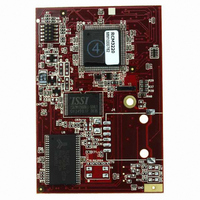
MODULE RABBITCORE RCM3220
Manufacturer
Rabbit Semiconductor
Datasheet
1.20-101-0522.pdf
(96 pages)
Specifications of 20-101-0522
Module/board Type
MPU Core Module
Product
Microcontroller Modules
Core Processor
Rabbit 3000
Clock Speed
44.2 MHz
Interface Type
Ethernet, Serial
Flash
512 KB
Timers
10 x 8 bit, 1 x 10 bit
Operating Supply Voltage
3.15 V to 3.45 V
Board Size
69 mm x 47 mm x 22 mm
Core
RCM3220
Processor Series
RCM3200
For Use With/related Products
RCM3220
Lead Free Status / RoHS Status
Lead free / RoHS Compliant
Other names
316-1098


2.2 Serial Communication
The RCM3200 board does not have an RS-232 or an RS-485 transceiver directly on the
board. However, an RS-232 or RS-485 interface may be incorporated on the board the
RCM3200 is mounted on. For example, the Prototyping Board has a standard RS-232
transceiver chip.
2.2.1 Serial Ports
There are six serial ports designated as Serial Ports A, B, C, D, E, and F. All six serial
ports can operate in an asynchronous mode up to the baud rate of the system clock divided
by 8. An asynchronous port can handle 7 or 8 data bits. A 9th bit address scheme, where
an additional bit is sent to mark the first byte of a message, is also supported. Serial Ports
A, B, C, and D can also be operated in the clocked serial mode. In this mode, a clock line
synchronously clocks the data in or out. Either of the two communicating devices can sup-
ply the clock.
Serial Ports E and F can also be configured as SDLC/HDLC serial ports. The IrDA proto-
col is also supported in SDLC format by these two ports.
2.2.2 Ethernet Port
Figure 4 shows the pinout for the RJ-45 Ethernet port (J4). Note that some Ethernet con-
nectors are numbered in reverse to the order used here.
ETHERNET
Figure 4. RJ-45 Ethernet Port Pinout
Three LEDs are placed next to the RJ-45 Ethernet
jack, one to indicate an Ethernet link (
LNK
), one to
indicate Ethernet activity (
), and one to indi-
ACT
cate when the RCM3200 is connected to a function-
ing 100Base-T network (
).
SPD
The transformer/connector assembly ground is con-
nected to the RCM3200 printed circuit board digital
ground via a 0
resistor, R42, as shown in Figure 5.
Figure 5. Isolation Resistor R42
The RJ-45 connector is shielded to minimize EMI
effects to/from the Ethernet signals.
12
RabbitCore RCM3200
Related parts for 20-101-0522
Image
Part Number
Description
Manufacturer
Datasheet
Request
R

Part Number:
Description:
COMPUTER SGL-BRD BL2500 29.4MHZ
Manufacturer:
Rabbit Semiconductor
Datasheet:

Part Number:
Description:
COMPUTER SGL-BRD BL2500 29.4MHZ
Manufacturer:
Rabbit Semiconductor
Datasheet:

Part Number:
Description:
DISPLAY GRAPHIC 12KEY PROG OP670
Manufacturer:
Rabbit Semiconductor
Datasheet:
Part Number:
Description:
DISPLAY GRAPHIC 12KEY ETH OP6700
Manufacturer:
Rabbit Semiconductor
Datasheet:

Part Number:
Description:
COMPUTER SINGLE-BOARD BL2030
Manufacturer:
Rabbit Semiconductor
Part Number:
Description:
COMPUTER SGL-BOARD ETH BL2010
Manufacturer:
Rabbit Semiconductor

Part Number:
Description:
MODULE OP6810 W/O ETH/MEM EXPANS
Manufacturer:
Rabbit Semiconductor
Datasheet:
Part Number:
Description:
COMPUTER SINGLE-BOARD BL2020
Manufacturer:
Rabbit Semiconductor
Part Number:
Description:
COMPUTER BL2010 W/FRICTION LOCK
Manufacturer:
Rabbit Semiconductor
Part Number:
Description:
COMPUTER BL2020 W/FRICTION LOCK
Manufacturer:
Rabbit Semiconductor
Part Number:
Description:
COMPUTER SGL-BRD BL2500 44.2MHZ
Manufacturer:
Rabbit Semiconductor
Datasheet:
Part Number:
Description:
COMPUTER SGL-BOARD FULL BL2000
Manufacturer:
Rabbit Semiconductor

Part Number:
Description:
COMPUTER SINGLE-BOARD BL2110
Manufacturer:
Rabbit Semiconductor

Part Number:
Description:
COMPUTER SGL-BRD 29.4MHZ BL2610
Manufacturer:
Rabbit Semiconductor
Datasheet:
Part Number:
Description:
INTERFACE OP6800 512K FLASH&SRAM
Manufacturer:
Rabbit Semiconductor
Datasheet: