20-101-1131 Rabbit Semiconductor, 20-101-1131 Datasheet
20-101-1131
Specifications of 20-101-1131


Related parts for 20-101-1131


20-101-1131 Summary of contents
Page 1
... RabbitCore RCM4200 C-Programmable Analog Core Module with Serial Flash and Ethernet User’s Manual 019–0159 • 090508–E ...
Page 2
... RabbitCore RCM4200 User’s Manual Part Number 019-0159 • 090508–E • Printed in U.S.A. ©2006–2009 Digi International Inc. • All rights reserved. No part of the contents of this manual may be reproduced or transmitted in any form or by any means without the express written permission of Digi International. ...
Page 3
... Online Documentation ..................................................................................................................6 Chapter 2. Getting Started 2.1 Install Dynamic C .................................................................................................................................7 2.2 Hardware Connections..........................................................................................................................8 2.2.1 Step 1 — Prepare the Prototyping Board for Development..........................................................8 2.2.2 Step 2 — Attach Module to Prototyping Board............................................................................9 2.2.3 Step 3 — Connect Programming Cable ......................................................................................10 2.2.4 Step 4 — Connect Power ............................................................................................................11 2.3 Run a Sample Program .......................................................................................................................12 2 ...
Page 4
... A/D Converter (RCM4200 only) ....................................................................................................... 41 4.4.1 A/D Converter Power Supply..................................................................................................... 43 4.5 Other Hardware .................................................................................................................................. 44 4.5.1 Clock Doubler ............................................................................................................................ 44 4.5.2 Spectrum Spreader...................................................................................................................... 44 4.6 Memory .............................................................................................................................................. 45 4.6.1 SRAM......................................................................................................................................... 45 4.6.2 Flash EPROM............................................................................................................................. 45 4.6.3 Serial Flash ................................................................................................................................. 45 Chapter 5. Software Reference 5.1 More About Dynamic C ..................................................................................................................... 47 5.2 Dynamic C Function Calls ................................................................................................................ 49 5 ...
Page 5
... B.4 Using the Prototyping Board............................................................................................................107 B.4.1 Adding Other Components.......................................................................................................109 B.4.2 Measuring Current Draw..........................................................................................................109 B.4.3 Analog Features (RCM4200 only) ...........................................................................................110 B.4.3.1 A/D Converter Inputs ...................................................................................................... 110 B.4.3.2 Thermistor Input .............................................................................................................. 112 B.4.3.3 A/D Converter Calibration .............................................................................................. 112 B.4.4 Serial Communication ..............................................................................................................113 B.4.4.1 RS-232 ............................................................................................................................. 114 B ...
Page 6
... RabbitCore RCM4200 ...
Page 7
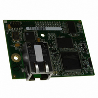
... Rabbit 4000’s internal real-time clock and 512K of static RAM. One 50-pin header brings out the Rabbit 4000 I/O bus lines, parallel ports, A/D converter channels, and serial ports ...
Page 8
... Combinations eight single-ended or four differential 12-bit analog inputs (RCM4200 only) • Alternate I/O bus can be configured for 8 data lines and 6 address lines (shared with parallel I/O lines), I/O read/write • 512K flash memory, 512K SRAM, and a fixed mass-storage flash-memory option that ...
Page 9
... Serial Ports • • The RCM4200 is programmed over a standard PC USB port through a programming cable supplied with the Development Kit. NOTE: The RabbitLink cannot be used to program RabbitCore modules based on the Rabbit 4000 microprocessor. Appendix A provides detailed specifications for the RCM4200. ...
Page 10
... Easy C-language program development and debugging • Rabbit Field Utility to download compiled Dynamic C .bin files, and cloning board options for rapid production loading of programs. • Generous memory size allows large programs with tens of thousands of lines of code, and substantial data storage. 4 ...
Page 11
... These Getting Started instructions included with the Development Kit will help you get your RCM4200 up and running so that you can run the sample programs to explore its capabilities and develop your own applications. ...
Page 12
... Online Documentation The online documentation is installed along with Dynamic C, and an icon for the docu- mentation menu is placed on the workstation’s desktop. Double-click this icon to reach the menu. If the icon is missing, use your browser to find and load folder, found in the Dynamic C installation folder. ...
Page 13
... The installation allows you to choose the COM port that will be used. The default selec- tion is COM1. You may select any available port for Dynamic C’s use. If you are not cer- tain which port is available, select COM1. This selection can be changed later within Dynamic C ...
Page 14
... Prepare the Prototyping Board for Development. 2. Attach the RCM4200 module to the Prototyping Board. 3. Connect the programming cable between the RCM4200 and the PC. 4. Connect the power supply to the Prototyping Board. 2.2.1 Step 1 — Prepare the Prototyping Board for Development Snap in four of the plastic standoffs supplied in the bag of accessory parts from the Devel- opment Kit in the holes at the corners as shown in Figure 2 ...
Page 15
... Press the module’s pins gently into the Prototyping Board socket—press down in the area above the header pins. For additional integrity, you may secure the RCM4200 to the stand- offs from the top using the remaining two screws and washers. ...
Page 16
... The programming cable connects the module to the PC running Dynamic C to download programs and to monitor the module during debugging. Connect the 10-pin connector of the programming cable labeled the RCM4200 as shown in Figure 4. Be sure to orient the marked (usually red) edge of the cable towards pin 1 of the connector. (Do not use the normal serial connection.) Figure 4 ...
Page 17
... AC adapter as shown in Figure 4, then press down on the plug until it clicks into place. Connect the AC adapter to 3-pin header J1 on the Prototyping Board as shown in Figure 4 above. The connector may be attached either way as long not offset to one side— the center pin always connected to the positive terminal, and either edge pin is ground. ...
Page 18
... Dynamic C Options > Project Options menu. (Select Code and BIOS in Flash RCM4210.) Click OK. If you are using a USB port to connect your computer to the RCM4200, click on the “Communications” tab and verify that port the USB programming cable. Click was assigned to the RS-232/USB converter. Open Device Manager > ...
Page 19
... The user's manual also provides complete hardware reference information and software function calls for the RCM4200 series of modules and the Prototyping Board. For advanced development topics, refer to the Dynamic C User’s Manual, also in the online documentation set. 2.4.1 Technical Support NOTE: If you purchased your RCM4200 through a distributor or through a Rabbit partner, contact the distributor or partner first for technical support ...
Page 20
... RabbitCore RCM4200 ...
Page 21
... NOTE: The sample programs assume that you have at least an elementary grasp of ANSI C. If you do not, see the introductory pages of the Dynamic C User’s Manual for a sug- gested reading list. In order to run the sample programs discussed in this chapter and elsewhere in this manual, 1. Your module must be plugged in to the Prototyping Board as described in Chapter 2, “ ...
Page 22
... Dynamic C STDIO window. Press “2” or “3” on your keyboard to select LED DS2 or DS3 on the Prototyping Board. Then follow the prompt in the Dynamic C or OFF. A logic low will light up the LED you selected. —demonstrates the use of assembly language to flash LEDs DS2 and • ...
Page 23
... Board are turned on and off when you press switches S2 and S3. S2 and S3 are controlled by PB4 and PB5 respectively. Once you have loaded and executed these five programs and have an understanding of how Dynamic C and the RCM4200 modules interact, you can move on and try the other sample programs, or begin building your own. User’s Manual ...
Page 24
... Web server and stores a log of • SERIAL_FLASHLOG.C hits on the home page of the serial flash “server.” This log can be viewed and cleared from a browser at http://10.10.6.100/. You will likely have to first “configure” your net- work interface card for a “10Base-T Half-Duplex,” “100Base-T Half-Duplex,” “ ...
Page 25
... Serial Port D for • FLOWCONTROL.C CTS/RTS flow control with serial data coming from Serial Port C (TxC) at 115,200 bps. The serial data received are displayed in the To set up the Prototyping Board, you will need to tie TxD and RxD ...
Page 26
... Since the J4 header locations on the two Prototyping Boards are connected with wires, there are no slip-on jumpers either Prototyping Board. —This program demonstrates transmitting and then receiving an • SWITCHCHAR.C ASCII string on Serial Ports C and D. It also displays the serial data received from both ports in the window ...
Page 27
... Once you have compiled and run this program, press and release switches the Prototyping Board. The data echoed between the serial ports will be displayed in the User’s Manual —This program demonstrates how to set up Serial Port E, STDIO IOCONFIG.EXE IOCONFIG.EXE folder for the 29 MHz RCM4210. ...
Page 28
... BIOS in RAM” compiler option. Compile and run this sample program once you have connected a positive voltage from 0– analog input (except LN7) on the Prototyping Board, and ground to GND. Follow the prompts in the Dynamic C STDIO window. Raw data and the computed equiv- alent voltages will be displayed ...
Page 29
... Feed options — Now compile and run this sample program. Verify that the message “Waiting, Please Send Data file” message is being display in the Tera Term display window before proceeding. Within Tera Term, select File-->Send File-->Path and filename option within the dialog box ...
Page 30
... Baud rate 19,200 bps, 8 bits, no parity, 1 stop bit • Enable • Feed options — Follow the remaining steps carefully in Tera Term to avoid overwriting previously saved calibration data when using same the file name. • Enable the File APPEND • Select the OPEN Tera Term is now ready to log all data received on the serial port to the file you specified ...
Page 31
... Set the real-time clock using the the Dynamic C SAMPLES\RTCLOCK sample program in the Dynamic C RTC_TEST.C additional examples of how to read and set the real-time clock. User’s Manual SETRTCKB.C folder, using the onscreen prompts. The SAMPLES\RTCLOCK sample program from folder provides ...
Page 32
... RabbitCore RCM4200 ...
Page 33
... Chapter 4 describes the hardware components and principal hardware subsystems of the RCM4200. Appendix A, “RCM4200 Specifica- tions,” provides complete physical and electrical specifications. Figure 5 shows the Rabbit-based subsystems designed into the RCM4200. User’s Manual 4. H ARDWARE Figure 5. RCM4200 Subsystems R EFERENCE 27 ...
Page 34
... RCM4200 Digital Inputs and Outputs Figure 6 shows the RCM4200 pinouts for header J2. standard 2 × 25 IDC header with a nominal 1.27 mm pitch. Headers Figure 6. RCM4200 Pinout RabbitCore RCM4200 ...
Page 35
... Figure 7 shows the use of the Rabbit 4000 microprocessor ports in the RCM4200 modules. Figure 7. Use of Rabbit 4000 Ports The ports on the Rabbit 4000 microprocessor used in the RCM4200 are configurable, and so the factory defaults can be reconfigured. Table 2 lists the Rabbit 4000 factory defaults and the alternate configurations. User’ ...
Page 36
... Table 2. RCM4200 Pinout Configurations Pin Pin Name Default Use 1 +3.3 V_IN 2 GND 3 /RES_OUT Reset output 4 /IORD Output 5 /IOWR Output 6 /RESET_IN Input 7 VBAT_EXT Battery input 8–15 PA[0:7] Input/Output 16 PB0 Input/Output 17 PB1 Input/Output 18 PB2 Input/Output 19 PB3 Input/Output 20 PB4 Input/Output 21 PB5 Input/Output 22 PB6 Input/Output ...
Page 37
... Table 2. RCM4200 Pinout Configurations (continued) Pin Pin Name Default Use 24 PC0 Input/Output 25 PC1 Input/Output 26 PC2 Input/Output 27 PC3 Input/Output 28 PC4 Input/Output 29 PC5 Input/Output 30 PC6 Input/Output 31 PC7 Input/Output 32 PE0 Input/Output User’s Manual Alternate Use TXD I/O Strobe I0 Timer C0 TCLKF Serial Port D RXD/TXD ...
Page 38
... Table 2. RCM4200 Pinout Configurations (continued) Pin Pin Name Default Use 33 PE1 Input/Output 34 PE2 Input/Output 35 PE3 Input/Output 36 PE4 Input/Output 37 PE5/SMODE0 Input/Output 38 PE6/SMODE1 Input/Output 39 PE7/STATUS Input/Output 32 Alternate Use I/O Strobe I1 A21 Timer C1 RXD/RCLKF INT1 QRD1A Input Capture I/O Strobe I2 A22 Timer C2 Ethernet enable ...
Page 39
... Table 2. RCM4200 Pinout Configurations (continued) Pin Pin Name Default Use 40–47 LN[0:7] Analog Input 40 PD0 Input/Output 41 PD1 Input/Output 42 PD2 Input/Output 43 PD3 Input/Output 44 PD4 Input/Output 45 PD5 Input/Output User’s Manual Alternate Use A/D converter (RCM4200 only) I/O Strobe I0 Timer C0 D8 INT0 SCLKD/TCLKF ...
Page 40
... Parallel Port A can also be used as an external I/O data bus to isolate external I/O from the main data bus. Parallel Port B pins PB2–PB7 can also be used as an auxiliary address bus. When using the auxiliary I/O bus for any reason, you must add the following line at the beginning of your program ...
Page 41
... Serial Port C is used as a clocked serial port. Since this serial port is available for synchronous serial communication on either RCM4200 model, you will lose the serial flash’s functionality if you try to use the serial port in the asynchronous mode. NOTE: Since Serial Port C is shared with the serial flash, exercise care if you attempt to use Serial Port C for other serial communication ...
Page 42
... PD2, PE2, PE7, PC7 4.2.1.1 Using the Serial Ports The receive lines on the RCM4200 serial ports do not have pull-up resistors. If you are using the serial ports without a receiver chip (for example, for RS-422, RS-232, or RS-485 serial communication), the absence of a pull-up resistor on the receive line will likely lead to line breaks being generated since line breaks are normally generated whenever the receive line is pulled low ...
Page 43
... Figure 8 shows the pinout for the RJ-45 Ethernet port (J3). Note that some Ethernet con- nectors are numbered in reverse to the order used here. Figure 8. RJ-45 Ethernet Port Pinout Three LEDs are placed next to the RJ-45 Ethernet jack, one to indicate Ethernet link/activity ( ), one to indicate when the RCM4200 is connected to a functioning 100Base-T LINK/ACT network ( ), and one ( SPEED duplex mode (steady on) or that a half-duplex connection is experiencing collisions (blinks) ...
Page 44
... Alternate Uses of the Programming Port All three Serial Port A signals are available as • a synchronous serial port • an asynchronous serial port, with the clock line usable as a general CMOS I/O pin The programming port may also be used as a serial port via the programming cable. ...
Page 45
... Programming Cable The programming cable is used to connect the programming port of the RCM4200 serial COM port. The programming cable converts the RS-232 voltage levels used by the PC serial port to the CMOS voltage levels used by the Rabbit 4000. When the connector on the programming cable is connected to the programming PROG port on the RCM4200, programs can be downloaded and debugged over the serial interface ...
Page 46
... CAUTION: Power to the Prototyping Board or other boards should be disconnected when removing or installing your RCM4200 module to protect against inadvertent shorts across the pins or damage to the RCM4200 if the pins are not plugged in cor- rectly. Do not reapply power until you have verified that the RCM4200 module is plugged in correctly ...
Page 47
... The actual voltage range for a signal going to the A/D converter input is also affected by the 10, 16, and 20 V/V software-programmable gains available on each channel of the ADS7870 A/D converter. Thus, you must scale the analog signal with an attenuator circuit and a software-programmable gain so that the actual input presented to the A/D converter is within the range limits of the ADS7870 A/D converter chip (- ...
Page 48
... Use a separate buffer amplifier if you need to supply any load current. The A/D converter’s CONVERT pin is available on pin 48 of header J2 and can be used as a hardware means of forcing the A/D converter to start a conversion cycle at a specific time. ...
Page 49
... A/D Converter Power Supply The analog section is isolated from digital noise generated by other components by way of a low-pass filter composed of C1, L1, and C86 on the RCM4200 as shown in Figure 13. The +V analog power supply powers the A/D converter chip. Figure 13. Analog Supply Circuit User’s Manual ...
Page 50
... Other Hardware 4.5.1 Clock Doubler The RCM4200 takes advantage of the Rabbit 4000 microprocessor’s internal clock doubler. A built-in clock doubler allows half-frequency crystals to be used to reduce radiated emissions. The 58.98 MHz frequency specified for the RCM4200 model is generated using a 29.49 MHz crystal. ...
Page 51
... Memory 4.6.1 SRAM All RCM4200 modules have 512K of battery-backed data SRAM installed at U10, and the RCM4200 model has 512K of fast SRAM installed at U12. 4.6.2 Flash EPROM All RCM4200 modules also have 512K of flash EPROM installed at U11. NOTE: Rabbit Semiconductor recommends that any customer applications should not be constrained by the sector size of the flash EPROM since it may be necessary to change the sector size in the future ...
Page 52
... RabbitCore RCM4200 ...
Page 53
... Dynamic C is contained in the Dynamic C User’s Manual. You have a choice of doing your software development in the flash memory or in the static SRAM included on the RCM4200. The flash memory and SRAM options are selected with the Options > Program Options > Compiler The advantage of working in RAM is to save wear on the flash memory, which is limited to about 100,000 write cycles ...
Page 54
... C, SPI, GPS, file system. LCD display and keypad drivers. • Powerful language extensions for cooperative or preemptive multitasking • Loader utility program to load binary images into Rabbit targets in the absence of Dynamic C. • Provision for customers to create their own source code libraries and augment on-line help by creating “ ...
Page 55
... Dynamic C Function Calls 5.2.1 Digital I/O The RCM4200 was designed to interface with other systems, and so there are no drivers written specifically for the I/O. The general Dynamic C read and write functions allow you to customize the parallel I/O to meet your specific needs. For example, use WrPortI(PEDDR, & ...
Page 56
... This flag is also stored in the battery-backed SRAM. When a protected variable is updated, the “inactive” copy is modified, and is made “active” only when the update is 100% complete. This assures the integrity of the data in case a reset or a power failure occurs during the update process ...
Page 57
... RCM4200 as a master for cloning. An RCM4200 master will not run the appli- cation, and further debugging is not possible as long as the macro is set to 1. Any cloned RCM4200 modules will be “sterile,” meaning that they can- not be used as a master for cloning. To develop and debug an application on an RCM4200, comment out the CL_FORCE_MASTER_MODE NOTE: Instead of defining this macro is your application, you may simply add the line CL_FORCE_MASTER_MODE=1 under the Dynamic C Options > ...
Page 58
... DESCRIPTION Call this function at the beginning of your program. This function initializes Parallel Ports A through E for use with the Prototyping Board, and on the RCM4200 model loads the stored calibration constants for the A/D converter. This function call is intended for demonstration purposes only, and can be modified for your applications. ...
Page 59
... These function calls can be found in the Dynamic C void timedAlert(unsigned long timeout); DESCRIPTION Polls the real-time clock until a timeout occurs. The RCM4200 will low-power mode during this time. Once the timeout occurs, this function call will enable the normal power source. PARAMETER ...
Page 60
... Analog Inputs (RCM4200 only) The function calls used with the Prototyping Board features and the A/D converter on the RCM4200 model are in the Dynamic C Dynamic C v. 10.07 or later is required to use the A/D converter function calls. unsigned int anaInConfig(unsigned int instructionbyte, unsigned int cmd, long brate); ...
Page 61
... Enter 0 if you are performing a read operation. For example, the serial clock transfer rate of 9600 to 115,200 bytes per second. brate brate must be set the first time this function is called. Enter 0 for this parameter thereafter, for example, ...
Page 62
... An exception error will occur if Direct Mode bit D7 is not set. PARAMETERS contains a gain code and a channel code as follows. cmd Use the following calculation and the tables below to determine 56 anaInDriver D7—1; D6–D4—Gain Code; D3–D0—Channel Code cmd = 0x80 | (gain_code*16) + channel_code Gain Gain Code Multiplier 0 ×1 1 × ...
Page 63
... Negative input is ground. † Not accessible on Prototyping Board ‡ Not accessible on Prototyping Board RETURN VALUE A value corresponding to the voltage on the analog input channel: 0–2047 for 11-bit conversions -2048–2047 for 12-bit conversions ADTIMEOUT (-4095) if the conversion is incomplete or busy bit timeout ...
Page 64
... Prototyping Board): gaincode Gain Code anaIn SINGLE—single-ended input DIFF—differential input mAMP—4–20 mA input SINGLE DIFF +AIN0 +AIN0 -AIN1 +AIN1 +AIN1 -AIN0* +AIN2 +AIN2 -AIN3 +AIN3 +AIN3 -AIN2* +AIN4 +AIN4 -AIN5 +AIN5 +AIN5 -AIN4* ...
Page 65
... RETURN VALUE A value corresponding to the voltage on the analog input channel: 0–2047 for single-ended conversions -2048–2047 for differential conversions ADTIMEOUT (-4095) if the conversion is incomplete or busy bit timeout ADOVERFLOW (-4096) for overflow or out of range SEE ALSO anaIn, anaInConfig, anaInDriver User’s Manual ...
Page 66
... Not accessible on Prototyping Board. 60 anaInCalib SINGLE—single-ended input DIFF—differential input mAMP—4–20 mA input SINGLE DIFF +AIN0 +AIN0 -AIN1 +AIN1 +AIN1 -AIN0* +AIN2 +AIN2 -AIN3 +AIN3 +AIN3 -AIN2* +AIN4 +AIN4 -AIN5 +AIN5 +AIN5 -AIN4* +AIN6 ...
Page 67
... mA) the second A/D converter channel raw count value (0–2047) value2 the voltage or current corresponding to the first A/D converter volts2 channel value ( mA) RETURN VALUE 0 if successful not able to make calibration constants. SEE ALSO anaIn, anaInVolts, anaInmAmps, anaInDiff, anaInCalib, brdInit User’ ...
Page 68
... PARAMETERS the channel number ( corresponding to LN0 to LN7. channel Channel Code Negative input is ground. † Applies to Prototyping Board. ‡ Used for thermistor in sample program. the gain code (applies only to Prototyping Board): gaincode Gain Code Applies to Prototyping Board. 62 anaInVolts ...
Page 69
... RETURN VALUE A voltage value corresponding to the voltage on the analog input channel. ADTIMEOUT (-4095) if the conversion is incomplete or busy bit timeout. ADOVERFLOW (-4096) for overflow or out of range. SEE ALSO anaInCalib, anaIn, anaInmAmps, brdInit User’s Manual 63 ...
Page 70
... Gain Voltage Range Multiplier (V) ×1 -22.5 – +22.5 ×2 -11.25 – +11.25 ×4 -5.6 – +5.6 ×5 -4.5 – +4.5 ×8 -2.8 – +2.8 ×10 -2.25 – +2.25 ×16 -1.41 – +1.41 ×20 -1.126 – +1.126 * RabbitCore RCM4200 ...
Page 71
... RETURN VALUE A voltage value corresponding to the voltage differential on the analog input channel. ADTIMEOUT (-4095) if the conversion is incomplete or busy bit timeout. ADOVERFLOW (-4096) for overflow or out of range. SEE ALSO anaInCalib, anaIn, anaInmAmps, brdInit User’s Manual 65 ...
Page 72
... PARAMETERS the channel number ( corresponding to LN0 to LN7. channel RETURN VALUE A current value between 4.00 and 20.00 mA corresponding to the current on the analog input channel. ADTIMEOUT (-4095) if the conversion is incomplete or busy bit timeout. ADOVERFLOW (-4096) for overflow or out of range. SEE ALSO ...
Page 73
... ALLCHAN * Not accessible on Prototyping Board. User’s Manual anaInEERd SINGLE—single-ended input DIFF—differential input mAMP—4–20 mA input SINGLE DIFF +AIN0 +AIN0 -AIN1 +AIN1 +AIN1 -AIN0* +AIN2 +AIN2 -AIN3 +AIN3 +AIN3 -AIN2* +AIN4 +AIN4 -AIN5 +AIN5 +AIN5 -AIN4* +AIN6 ...
Page 74
... ALLCHAN. Gain Code Applies to Prototyping Board. RETURN VALUE 0 if successful address is invalid or out of range. SEE ALSO anaInEEWr, anaInCalib 68 * Gain Voltage Range Multiplier (V) ×1 0–22.5 ×2 0–11.25 ×4 0–5.6 ×5 0–4.5 ×8 0–2.8 ×10 0–2.25 ×16 0–1.41 ×20 0–1.126 RabbitCore RCM4200 ...
Page 75
... ALLCHAN * Not accessible on Prototyping Board. User’s Manual anaInEEWr SINGLE—single-ended input DIFF—differential input mAMP—4–20 mA input SINGLE DIFF +AIN0 +AIN0 -AIN1 +AIN1 +AIN1 -AIN0* +AIN2 +AIN2 -AIN3 +AIN3 +AIN3 -AIN2* +AIN4 +AIN4 -AIN5 +AIN5 +AIN5 -AIN4* +AIN6 ...
Page 76
... ALLCHAN. Gain Code Applies to Prototyping Board. RETURN VALUE 0 if successful -1 if address is invalid or out of range. SEE ALSO anaInEEWr, anaInCalib 70 * Gain Voltage Range Multiplier (V) ×1 0–22.5 ×2 0–11.25 ×4 0–5.6 ×5 0–4.5 ×8 0–2.8 ×10 0–2.25 ×16 0–1.41 ×20 0–1.126 RabbitCore RCM4200 ...
Page 77
... Web, and other select libraries. NOTE: Version 2.10 or later of the Dynamic C FAT file system module is required for the RCM4200 modules. Each Dynamic C add-on module has complete documentation and sample programs to illustrate the functionality of the software calls in the module. Visit our Web site at www ...
Page 78
... RabbitCore RCM4200 ...
Page 79
... RCM4200 module’s Ethernet port at this time. Before proceeding you will need to have the following items. • If you don’t have Ethernet access, you will need at least a 10Base-T Ethernet card (available from your favorite computer supplier) installed in a PC. • Two RJ-45 straight-through Ethernet cables and a hub RJ-45 crossover Ethernet cable ...
Page 80
... Connect the AC adapter and the serial programming cable as shown in Chapter 2, “Get- ting Started.” 2. Ethernet Connections There are four options for connecting the RCM4200 module to a network for develop- ment and runtime purposes. The first two options permit total freedom of action in selecting network addresses and use of the “ ...
Page 81
... Internet and the internal network. These machines include a combination of proxy servers and firewalls that filter and multiplex Internet traf- fic. In the configuration below, the RCM4200 could be given a fixed address so any of the computers on the local network would be able to contact it. It may be possible to configure ...
Page 82
... If your system administrator can give you an Ethernet cable along with its IP address, the netmask and the gateway address, then you may be able to run the sample programs with- out having to setup a direct connection between your computer and the RCM4200. You will also need the IP address of the nameserver, the name or IP address of your mail server, and your domain name for some of the sample programs ...
Page 83
... The highest address (216.102.126.255) is used as a broadcast address. Usually one other address is used for the address of the gateway out of the network. This leaves 256 - 3 = 253 available IP addresses for the example given. User’s Manual N IP addresses in a local network. The netmask (also 8 ...
Page 84
... Each RCM4200 RabbitCore module has its own unique MAC address, which consists of the prefix 0090C2 followed by a code that is unique to each RCM4200 module. For exam- ple, a MAC address might be 0090C2C002C0. TIP: You can always obtain the MAC address on your module by running the sample program DISPLAY_MAC ...
Page 85
... The DHCP server may try to give you the same address each time, but a fixed IP address is usually not guaranteed. If you are not concerned about accessing the RCM4200 from the Internet, you can place the RCM4200 on the internal network using an IP address assigned either statically or through DHCP. User’ ...
Page 86
... If you want users on the Internet to communicate with your RCM4200, you have several options. You can either place the RCM4200 directly on the Internet with a real Internet address or place it behind the firewall. If you place the RCM4200 behind the fire- wall, you need to configure the firewall to translate and forward packets from the Internet to the RCM4200 ...
Page 87
... We have provided a number of sample programs demonstrating various uses of TCP/IP for networking embedded systems. These programs require you to connect your PC and the RCM4200 module together on the same network. This network can be a local private net- work (preferred for initial experimentation and debugging connection via the Internet. ...
Page 88
... If you would like to change the default values, for example, to use an IP 10.10.6.1 address of for the RCM4200 module, and 10.1.1.2 edit the values in the section that directly follows the “General Configuration” com- ment in the TCP_CONFIG.LIB directory. 3. You can create a CUSTOM_CONFIG.LIB than 100 ...
Page 89
... Half-Duplex” “Auto-Negotiation” connection on the “Advanced” tab. NOTE: Your network interface card will likely have a different name. 3. Now select the IP Address click on “Properties” to assign an IP address to your computer (this will disable “obtain an IP address automatically”): IP Address : 10.10.6.101 Netmask : 255.255.255.0 Default gateway : 10 ...
Page 90
... BROWSELED.C Two “device LEDs” are created along with two buttons to toggle them. Users can use their Web browser to change the status of the lights. The DS2 and DS3 LEDs on the Prototyping Board will match those on the Web page. As long as you have not modified ...
Page 91
... Where From Here? NOTE: If you purchased your RCM4200 through a distributor or through a Rabbit partner, contact the distributor or partner first for technical support. If there are any problems at this point: • Use the Dynamic C Help • Check the Rabbit Semiconductor Technical Bulletin Board and forums at www.rabbit.com/support/bb/ • ...
Page 92
... RabbitCore RCM4200 ...
Page 93
... A A. RCM4200 S PPENDIX Appendix A provides the specifications for the RCM4200, and describes the conformal coating. User’s Manual PECIFICATIONS 87 ...
Page 94
... A.1 Electrical and Mechanical Characteristics Figure A-1 shows the mechanical dimensions for the RCM4200. Figure A-1. RCM4200 Dimensions NOTE: All measurements are in inches followed by millimeters enclosed in parentheses. All dimensions have a manufacturing tolerance of ±0.01" (0.25 mm). 88 RabbitCore RCM4200 ...
Page 95
... It is recommended that you allow for an “exclusion zone” of 0.04" (1 mm) around the RCM4200 in all directions when the RCM4200 is incorporated into an assembly that includes other printed circuit boards. An “exclusion zone” of 0.08" (2 mm) is recom- mended below the RCM4200 when the RCM4200 is plugged into another assembly. ...
Page 96
... Table A-1 lists the electrical, mechanical, and environmental specifications for the RCM4200. Table A-1. RCM4200 Specifications Parameter Microprocessor EMI Reduction Ethernet Port Data SRAM Program Execution Fast SRAM Flash Memory Serial Flash Memory Backup Battery 25 parallel digital I/O lines: • configurable with four layers of ...
Page 97
... Table A-1. RCM4200 Specifications (continued) Parameter Serial Rate Slave port allows the RCM4200 to be used as an intelligent peripheral device Slave Interface slaved to a master processor Real Time Clock Timers Watchdog/Supervisor • 3 channels synchronized PWM with 10-bit counter Pulse-Width Modulators • 3 channels variable-phase or syn- ...
Page 98
... Integral Linearity Differential Linearity Dynamic Characteristics Throughput Rate Voltage Reference Accuracy Buffer Amp Source Current Buffer Amp Sink Current Short-Circuit Current 92 Test Conditions Typ 4 – 9 MΩ 7 MΩ 11 bits 12 bits ±1 LSB ±0.5 LSB 52 ksamples 2.048 V and 2.5 V ±0.05% ref 20 mA 200 µ ...
Page 99
... A.1.2 Headers The RCM4200 uses a header at J2 for physical connection to other boards × 25 SMT header with a 1.27 mm pin spacing. J1, the programming port × 5 header with a 1.27 mm pin spacing. Figure A-3 shows the layout of another board for the RCM4200 to be plugged into. These reference design values are relative to one of the mounting holes ...
Page 100
... V, 25°C All other I/O I DRIVE (except TXD+, TXDD+, TXD-, TXDD-) 94 Parameter Maximum Rating -40° to +85°C -55° to +125°C VDD IO (max. 3 –40°C to +85°C, VDD A Min 3 Typ Max 3.3 V 3.6 V 1.8 V 1.90 V 2.0 V ...
Page 101
... I/O Ports Parallel Ports Table A-6 lists the external capacitive bus loading for the various RCM4200 output ports. Be sure to add the loads for the devices you are using in your custom system and verify that they do not exceed the values in Table A-6. ...
Page 102
... Figure A-4 shows a typical timing diagram for the Rabbit 4000 microprocessor external I/O read and write cycles. Figure A-4. External I/O Read and Write Cycles—No Extra Wait States NOTE: /IOCSx can be programmed to be active low (default) or active high. 96 RabbitCore RCM4200 ...
Page 103
... The measurements are taken at the 50% points under the following conditions. • -40°C to 85° VDD • Internal clock to nonloaded CLK pin delay ≤ 85°C/3.0 V The clock to address output delays are similar, and apply to the following delays. • the clock to address delay adr • ...
Page 104
... A.5 Conformal Coating The areas around the 32 kHz real-time clock crystal oscillator have had the Dow Corning silicone-based 1-2620 conformal coating applied. The conformally coated area is shown in Figure A-5. The conformal coating protects these high-impedance circuits from the effects of moisture and contaminants over time. ...
Page 105
... A.6 Jumper Configurations Figure A-6 shows the header locations used to configure the various RCM4200 options via jumpers. Figure A-6. Location of RCM4200 Configurable Positions Table A-9 lists the configuration options. Table A-9. RCM4200 Jumper Configurations Header Description JP1 LN0 or PD0 on J2 pin 40 ...
Page 106
... Table A-9. RCM4200 Jumper Configurations (continued) Header Description JP7 LN3 or PD3 on J2 pin 43 JP8 Data SRAM Size JP9 LN1 or PD1 on J2 pin 41 PE5 or SMODE0 Output JP10 on J2 pin 37 PE6 or SMODE1 Output JP11 on J2 pin 38 PE7 or STATUS Output JP12 on J2 pin 39 Clocked Synchronous or ...
Page 107
... Appendix B describes the features and accessories of the Proto- typing Board, and explains the use of the Prototyping Board to demonstrate the RCM4200 and to build prototypes of your own circuits. The Prototyping Board has power-supply connections and also provides some basic I/O peripherals (RS-232, LEDs, and switches), as well as a prototyping area for more advanced hardware development ...
Page 108
... B.1 Introduction The Prototyping Board included in the Development Kit makes it easy to connect an RCM4200 module to a power supply and a PC workstation for development. It also pro- vides some basic I/O peripherals (RS-232, LEDs, and switches), as well as a prototyping area for more advanced hardware development. ...
Page 109
... I/O Switches and LEDs nected to the PB4 and PB5 pins of the RCM4200 module and may be read as inputs by sample applications. Two LEDs are connected to the PB2 and PB3 pins of the RCM4200 module, and may be driven as output indicators by sample applications ...
Page 110
... RS-232 serial ports are available on the Prototyp- RS-232 • ing Board at header J4. A 10-pin 0.1" pitch header strip installed at J4 allows you to connect a ribbon cable that leads to a standard DE-9 serial connector. • Current Measurement Option bottom side of the Prototyping Board and install a 1 × 2 header strip from the Develop- ment Kit to allow you to use an ammeter across the pins to measure the current drawn from the +5 V supply ...
Page 111
... B.2 Mechanical Dimensions and Layout Figure B-2 shows the mechanical dimensions and layout for the Prototyping Board. Figure B-2. Prototyping Board Dimensions User’s Manual 105 ...
Page 112
... Prototyping Area Connectors B.3 Power Supply The RCM4200 requires a regulated 3.0 V – 3 power source to operate. Depending on the amount of current required by the application, different regulators can be used to supply this voltage. The Prototyping Board has an onboard +5 V switching power regulator from which a +3 ...
Page 113
... The Prototyping Board comes with the basic components necessary to demonstrate the operation of the RCM4200. Two LEDs (DS2 and DS3) are connected to PB2 and PB3, and two switches (S2 and S3) are connected to PB4 and PB5 to demonstrate the interface to the Rabbit 4000 microprocessor ...
Page 114
... The holes in the prototyping area are spaced at 0.1" (2.5 mm). +3 and GND traces run along the top edge of the prototyping area for easy access. Small to medium circuits can be prototyped using point-to-point wiring with AWG wire between the proto- typing area, the +3 and GND traces, and the surrounding area where surface- ...
Page 115
... Figure B-5. Prototyping Board Current-Measurement Option NOTE: Once you have cut the trace below header location JP1 or JP2, you must either be using the ammeter or have a jumper in place in order for power to be delivered to the Prototyping Board. User’s Manual 109 ...
Page 116
... B.4.3 Analog Features (RCM4200 only) The Prototyping Board has typical support circuitry installed to complement the ADS7870 A/D converter on the RCM4200 model (the A/D converter is not available on the RCM4210 model). B.4.3.1 A/D Converter Inputs Figure B-6 shows a pair of A/D converter input circuits. The resistors form an approx. 11:1 attenuator, and the capacitor filters noise pulses from the A/D converter input. The 470 Ω ...
Page 117
... V. This input is intended to be used for a thermistor that you may install at header location JP25 also possible to read a negative voltage on LN0_IN–LN5_IN by moving the 0 Ω jumper (see Figure B-6) on header JP23 or JP24 associated with the A/D converter input from analog ground to the reference voltage generated and buffered by the A/D converter. Adjacent input channels are paired ...
Page 118
... Sample programs are available to illustrate how to read and calibrate the various A/D inputs for the single-ended operating mode. Mode Single-Ended, one channel Single-Ended, all channels 112 sample program, which demon- THERMISTOR.C @ 25° kΩ and β 25/85 = 3965. Be sure Read — AD_CAL_CHAN.C AD_RDVOLT_ALL.C AD_CAL_ALL.C Calibrate RabbitCore RCM4200 ...
Page 119
... B.4.4 Serial Communication The Prototyping Board allows you to access the serial ports from the RCM4200 module. Table B-5 summarizes the configuration options. Note that Serial Ports E can be used only when the RCM4210 is installed on the Prototyping Board. Table B-5. Prototyping Board Serial Port Configurations ...
Page 120
... SERA_RTS_SHADOW—Shadow register for the RTS line's parallel port (e.g., PCDRShadow). SERA_RTS_BIT—The bit number for the RTS line. SERA_CTS_PORT—Data register for the parallel port that the CTS line is on (e.g., PCDRShadow). SERA_CTS_BIT—The bit number for the CTS line. ...
Page 121
... Figure B-8 shows the header locations used to configure the various Prototyping Board options via jumpers. Figure B-8. Location of Configurable Jumpers on Prototyping Board Table B-6 lists the configuration options using either jumpers or 0 Ω surface-mount resistors. Table B-6. RCM4200 Prototyping Board Jumper Configurations Header Description JP1 ...
Page 122
... Table B-6. RCM4200 Prototyping Board Jumper Configurations (continued) Header Description JP5 PC1/RxD/Switch S2 JP6 JP7 PC2/TxC/LED DS3 JP8 JP9 PC3/RxC/Switch S3 JP10 JP11 LN0 buffer/filter to RCM4200 JP12 PB2/LED DS2 JP13 LN1 buffer/filter to RCM4200 JP14 PB3/LED DS3 JP15 LN2 buffer/filter to RCM4200 JP16 PB4/Switch S2 JP17 ...
Page 123
... LN0_IN–LN3_IN JP25 Thermistor Location NOTE: Jumper connections JP3–JP10, JP12, JP14, JP16, JP18, JP23, and JP24 are made using 0 Ω surface-mounted resistors. Jumper connections JP11, JP13, JP15, JP17, and JP19–JP22 are made using 470 Ω surface-mounted resistors. User’s Manual Pins Connected 1– ...
Page 124
... RabbitCore RCM4200 ...
Page 125
... An RCM4200 with no loading at the outputs operating at 58.98 MHz typically draws 240 mA, and may draw up to 275 mA at 3.6 V and 85°C; the corresponding current draw for the RCM4210 is typically 200 mA, and up to 225 mA at 3.6 V and 85°C. C.1.1 Battery Backup The RCM4200 does not have a battery, but there is provision for a customer-supplied bat- tery to back up the data SRAM and keep the internal Rabbit 4000 real-time clock running ...
Page 126
... The drain on the battery by the RCM4200 is typically 7.5 µA when no other power is sup- plied 165 mA·h battery is used, the battery can last about 2.5 years: 165 mA·h ----------------------- - = 2.5 years. 7.5 µA The actual battery life in your application will depend on the current drawn by components not on the RCM4200 and on the storage capacity of the battery ...
Page 127
... The RCM4200 uses a reset generator to reset the Rabbit 4000 microprocessor when the volt- age drops below the voltage necessary for reliable operation. The reset occurs between 2.85 V and 3.00 V, typically 2.93 V. Since the RCM4200 will operate at voltages as low as 3.0 V, exercise care when operating close to the 3.0 V minimum voltage (for example, keep the power supply as close as possible to the RCM4200) since your RCM4200 could reset unintentionally ...
Page 128
... RabbitCore RCM4200 ...
Page 129
... User’s Manual C clock doubler ........................ 44 cloning .................................. 50 conformal coating ................. 98 D Development Kits ................... 5 RCM4200 Development Kit 5 AC adapter ...................... 5 Getting Started instruc- tions .............................. 5 programming cable ......... 5 digital I/O .............................. 28 function calls ..................... 49 digInAlert ...................... 53 timedAlert ..................... 53 I/O buffer sourcing and sinking limits ................ 95 memory interface ...
Page 130
... S sample programs ...................16 A/D converter AD_CAL_ALL.C ..22, 112 AD_CAL_CHAN.C 22, 112 AD_RDVOLT_ALL.C .............................22, 112 AD_SAMPLE.C ............22 THERMISTOR.C ..23, 112 A/D converter calibration DNLOADCALIB.C ......23 UPLOADCALIB.C .......23 getting to know the RCM4200 CONTROLLED.C .........16 FLASHLED1.C .............16 FLASHLED2.C .............16 TAMPERDETECTION.C .....................................17 TOGGLESWITCH.C ....17 how to run TCP/IP sample programs .................81, 82 how to set IP address .........82 onboard serial flash SERIAL_FLASHLOG.C .....................................18 SFLASH_INSPECT ...
Page 131
... TCP/IP BROWSELED.C .......... 84 DISPLAY_MAC.C ....... 78 PINGLED.C .................. 84 PINGME.C .................... 84 SMTP.C ........................ 84 USERBLOCK_CLEAR.C 49 USERBLOCK_INFO.C .... 49 serial communication ............ 35 function calls ..................... 49 Prototyping Board RS-232 ........................ 114 software PACKET.LIB ................ 49 RS232.LIB .................... 49 serial flash software FAT_CONFIG.LIB ....... 51 SFLASH.LIB ................ 51 SFLASH_FAT.LIB ....... 51 serial ports ............................. 35 Ethernet port ..................... 37 programming port ............. 38 receive line not pulled Serial Port B (A/D converter) ...
Page 132
... RabbitCore RCM4200 ...
Page 133
... RCM4200 Schematic www.rabbit.com/documentation/schemat/090-0241.pdf 090-0230 Prototyping Board Schematic www.rabbit.com/documentation/schemat/090-0230.pdf 090-0128 Programming Cable Schematic www.rabbit.com/documentation/schemat/090-0128.pdf 090-0252 USB Programming Cable Schematic www.rabbit.com/documentation/schemat/090-0252.pdf You may use the URL information provided above to access the latest schematics directly. User’s Manual S CHEMATICS 127 ...
Page 134
...