20-101-0672 Rabbit Semiconductor, 20-101-0672 Datasheet - Page 25
20-101-0672
Manufacturer Part Number
20-101-0672
Description
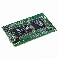
MODULE RABBITCORE RCM3600
Manufacturer
Rabbit Semiconductor
Datasheet
1.20-101-0673.pdf
(136 pages)
Specifications of 20-101-0672
Module/board Type
MPU Core Module
Product
Microcontroller Modules
Core Processor
Rabbit 3000
Clock Speed
22.1 MHz
Interface Type
Serial
Flash
512 KB
Timers
10 x 8 bit, 1 x 10 bit
Operating Supply Voltage
3 V to 3.6 V
Board Size
31 mm x 54 mm x 16 mm
Core
RCM3600
Processor Series
RCM3600
For Use With/related Products
RCM3600
Lead Free Status / RoHS Status
Lead free / RoHS Compliant
Other names
316-1102


•
•
•
Before running the next two sample programs,
connect your PC serial COM port to header J2 on the Prototyping Board as follows.
• Tx to RxE
• Rx to TxE
• GND to GND
Then connect pins 1–3 and 2–4 on header JP2 on the Prototyping Board.
Now start Tera Term on your PC. Once Tera Term is running, configure the serial parame-
ters as follows:
• Baud rate 19200, 8 bits, no parity, and 1 stop bit.
• Enable the "Local Echo" option.
• Set the line feed options to Receive = CR and Transmit = CR + LF.
Now press
Please Send Data file" is being display in Tera Term display window before proceeding.
From within Tera Term, select
OPEN option within the dialog box. Once the data file has been downloaded, it will indi-
cate whether the calibration data were written successfully.
•
Getting Started
AD_SAMPLE.C
The program will continuously display the voltage (average of 10 samples) that is
present on the A/D channels.
Before running this program, make sure that pins 3–5 are connected on headers JP5,
JP6, and JP7 on the Prototyping Board. No pins are connected on header JP8.
ANAINCONFIG.C
ended analog input values for display as voltages. The sample program uses the func-
tion call
Before running this program, make sure that pins 3–5 are connected on headers JP5,
JP6, and JP7 on the Prototyping Board. No pins are connected on header JP8. Also con-
nect PE4 on header J3 on the Prototyping Board to the CNVRT terminal on header J8;
if you are using this sample program as a template for your own program, be aware that
PE4 is also used as the IrDA FIR_SEL pin.
THERMISTOR.C
temperature for display to the
thermistor is the one included in the Development Kit whose values for beta, series
resistance, and resistance at standard temperature are given in the part specification.
Before running this program, install the thermistor into the AIN7 and AGND holes at
location J7 on the Prototyping Board.
DNLOADCALIB.C
back to simulated EEPROM in flash with using a serial utility such as Tera Term.
F9
anaInConfig()
to compile and run this program. Verify that the message "Waiting,
—Demonstrates how to use a low-level driver on single-ended inputs.
—Demonstrates how to use analog input THERM_IN7 to calculate
—Demonstrates how to use the Register Mode method to read single-
—Demonstrates how to retrieve analog calibration data to rewrite it
and the ADS7870 CONVERT line to accomplish this task.
File > Send File > Path and filename
STDIO
window. This sample program assumes that the
DNLOADCALIB.C
or
UPLOADCALIB.C
, then select the
,
19
Related parts for 20-101-0672
Image
Part Number
Description
Manufacturer
Datasheet
Request
R

Part Number:
Description:
COMPUTER SGL-BRD BL2500 29.4MHZ
Manufacturer:
Rabbit Semiconductor
Datasheet:

Part Number:
Description:
COMPUTER SGL-BRD BL2500 29.4MHZ
Manufacturer:
Rabbit Semiconductor
Datasheet:

Part Number:
Description:
DISPLAY GRAPHIC 12KEY PROG OP670
Manufacturer:
Rabbit Semiconductor
Datasheet:
Part Number:
Description:
DISPLAY GRAPHIC 12KEY ETH OP6700
Manufacturer:
Rabbit Semiconductor
Datasheet:

Part Number:
Description:
COMPUTER SINGLE-BOARD BL2030
Manufacturer:
Rabbit Semiconductor
Part Number:
Description:
COMPUTER SGL-BOARD ETH BL2010
Manufacturer:
Rabbit Semiconductor

Part Number:
Description:
MODULE OP6810 W/O ETH/MEM EXPANS
Manufacturer:
Rabbit Semiconductor
Datasheet:
Part Number:
Description:
COMPUTER SINGLE-BOARD BL2020
Manufacturer:
Rabbit Semiconductor
Part Number:
Description:
COMPUTER BL2010 W/FRICTION LOCK
Manufacturer:
Rabbit Semiconductor
Part Number:
Description:
COMPUTER BL2020 W/FRICTION LOCK
Manufacturer:
Rabbit Semiconductor
Part Number:
Description:
COMPUTER SGL-BRD BL2500 44.2MHZ
Manufacturer:
Rabbit Semiconductor
Datasheet:
Part Number:
Description:
COMPUTER SGL-BOARD FULL BL2000
Manufacturer:
Rabbit Semiconductor

Part Number:
Description:
COMPUTER SINGLE-BOARD BL2110
Manufacturer:
Rabbit Semiconductor

Part Number:
Description:
COMPUTER SGL-BRD 29.4MHZ BL2610
Manufacturer:
Rabbit Semiconductor
Datasheet:
Part Number:
Description:
INTERFACE OP6800 512K FLASH&SRAM
Manufacturer:
Rabbit Semiconductor
Datasheet: