20-101-0525 Rabbit Semiconductor, 20-101-0525 Datasheet - Page 38
20-101-0525
Manufacturer Part Number
20-101-0525
Description
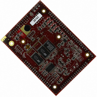
COMPUTER SINGLE-BOARD LP3500 FOX
Manufacturer
Rabbit Semiconductor
Specifications of 20-101-0525
Module/board Type
Single Board Computer Module
Product
Modules
Processor Type
Rabbit 3000
Sram
512 KB
Flash
512 KB
Timers
8 bit, 10 bit
Number Of I/os
26
Backup Battery
3 V Lithium Coin Type
Operating Voltage
3 V to 30 V
Board Size
93 mm x 66 mm x 11 mm
Description/function
Computer Module
For Use With/related Products
LP3500
Lead Free Status / RoHS Status
Lead free / RoHS Compliant
Other names
316-1115


Single-ended measurements are made by connecting the analog signal between an analog
input channel (AIN0–AIN7) and AGND. Differential measurements are made by connect-
ing a pair of differential analog signals to an adjacent pair of analog input channels
(AIN0–AIN1, …, AIN6–AIN7). The A/D converter is only capable of converting positive
voltages, and so will convert the difference between an adjacent pair of input channels,
and must be scaled for a voltage range appropriate for the voltage differences.
Table 7 lists the jumper configurations for header J3 used to set the 4–20 mA and the volt-
age measurement options.
The A/D converter inputs are factory-calibrated, and the calibration constants are stored in
flash memory. You may calibrate the A/D converter inputs at a later time using the software
functions described in Section 4.4.5, “A/D Converter Inputs.”
AIN7 can be used to monitor Vcc using the
be monitored in all the power modes, Vcc monitoring is particularly useful when the
LP3500 is being operated from an external battery to monitor the voltage being supplied
by the battery.
The
sumes about 500 µA.
engaged.
used) when the test is done to extend your battery life.
32
VccMonitorInit
CAUTION: If you have enabled the 4–20 mA current option on any of the AIN0–AIN3
NOTE: If you are using a fixed voltage range, you should recalibrate your LP3500 at that
Analog Input Channel
Turn off
channels, be careful with any voltage sources that you might connect to these inputs.
The voltage must be less than 2.5 V to keep the current across the 100 Ω resistor below
the maximum allowed current.
range.
Table 7. Header J3 Configuration for Analog I/O Options
AIN0
AIN1
AIN2
AIN3
VccMonitorInit()
The Vcc monitoring circuit itself consumes about 15 µA while it is
function requires the operation of the A/D converter, which con-
Jumper “parked” on pin 2
Jumper “parked” on pin 4
Jumper “parked” on pin 6
Jumper “parked” on pin 8
(Factory Default)
Voltage Option
(and the A/D converter if it is not going to be
VccMonitorInit
Pins 1–2 connected
Pins 3–4 connected
Pins 5–6 connected
Pins 7–8 connected
function. While Vcc can
4–20 mA Option
Fox (LP3500)
Related parts for 20-101-0525
Image
Part Number
Description
Manufacturer
Datasheet
Request
R

Part Number:
Description:
COMPUTER SGL-BRD BL2500 29.4MHZ
Manufacturer:
Rabbit Semiconductor
Datasheet:

Part Number:
Description:
COMPUTER SGL-BRD BL2500 29.4MHZ
Manufacturer:
Rabbit Semiconductor
Datasheet:

Part Number:
Description:
DISPLAY GRAPHIC 12KEY PROG OP670
Manufacturer:
Rabbit Semiconductor
Datasheet:
Part Number:
Description:
DISPLAY GRAPHIC 12KEY ETH OP6700
Manufacturer:
Rabbit Semiconductor
Datasheet:

Part Number:
Description:
COMPUTER SINGLE-BOARD BL2030
Manufacturer:
Rabbit Semiconductor
Part Number:
Description:
COMPUTER SGL-BOARD ETH BL2010
Manufacturer:
Rabbit Semiconductor

Part Number:
Description:
MODULE OP6810 W/O ETH/MEM EXPANS
Manufacturer:
Rabbit Semiconductor
Datasheet:
Part Number:
Description:
COMPUTER SINGLE-BOARD BL2020
Manufacturer:
Rabbit Semiconductor
Part Number:
Description:
COMPUTER BL2010 W/FRICTION LOCK
Manufacturer:
Rabbit Semiconductor
Part Number:
Description:
COMPUTER BL2020 W/FRICTION LOCK
Manufacturer:
Rabbit Semiconductor
Part Number:
Description:
COMPUTER SGL-BRD BL2500 44.2MHZ
Manufacturer:
Rabbit Semiconductor
Datasheet:
Part Number:
Description:
COMPUTER SGL-BOARD FULL BL2000
Manufacturer:
Rabbit Semiconductor

Part Number:
Description:
COMPUTER SINGLE-BOARD BL2110
Manufacturer:
Rabbit Semiconductor

Part Number:
Description:
COMPUTER SGL-BRD 29.4MHZ BL2610
Manufacturer:
Rabbit Semiconductor
Datasheet:
Part Number:
Description:
INTERFACE OP6800 512K FLASH&SRAM
Manufacturer:
Rabbit Semiconductor
Datasheet: